background image

2GL/2FV/2FW

1-5-3

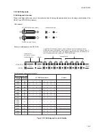
1-5-2 Self-diagnosis

(1) Self-diagnostic function

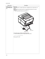
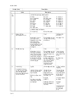
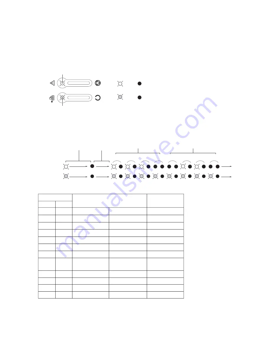
When a self diagnostics error occurs, the printer halts and displays the appropriate error code using a combination of the
READY and ATTENTION indicators.

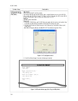
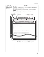
Figure 1-5-3 Self-diagnostic code indication

Off

Off

Lit

Lit

LED indicator

Indication example

E

6

1

1

1

1

1

0

0

1

E0

E1

E2

E3

E4

E6

F1

F2

F3

D9

7980

7990

F040

F010

F020

F030

2000

4000

4200

6050

6000
6010

F050

2 digits

4 digits

Self-diagnostic code

DA

1

1

0

0

0

0

0

1

1

1

0

0

1

0

0

1

1

1

0

1

0

0

0

1

1

1

0

1

1

0

0

1

1

1

1

0

0

0

0

1

1

1

1

1

0

0

0

1

1

1

0

0

1

1

0

1

1

1

0

1

0

1

0

1

1

1

0

1

1

1

0

1

1

0

0

0

1

1

1

A0

6400

1

0

1

0

0

0

0

0

1

1

0

0

1

0

1

1

ATTENTION indicator

Interval

(Hexadecimal)

Repeat

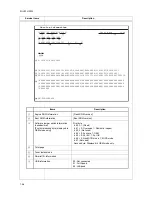
Example: self-diagnostic code: E6 (F050)

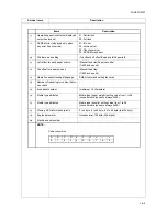
Self-diagnostic code conversion table

READY indicator (Green)

READY

ATTENTION indicator (Amber)

ATTENTION

0

7.3 s

2.4 s

16/18 ppm printers only

Remark

The ATTENTION indicator means 1 when it flashes in synchronization with the 
READY indicator which flashes at the interval of 1.2 second; and it means 0 when it 
turns off: This is repeated 8 times. Two digit self diagnostics codes are indicated in 8 
bits (2 digits hexadecimal) using the ATTENTION indicator.

Indicates the 
occurrence of a self 
diagnostics error.

Summary of Contents for LP 3118

Page 1: ...Service Manual Printer LP 3118 22 02 2005 ...

Page 2: ...Service Manual Printer LP 4118 22 02 2005 ...

Page 3: ... this symbol CAUTION Bodily injury or damage to property may result from insufficient attention to or incorrect compliance with warning messages using this symbol Symbols The triangle symbol indicates a warning including danger and caution The specific point of attention is shown inside the symbol General warning Warning of risk of electric shock Warning of high temperature indicates a prohibited ...

Page 4: ... or dusty place This may cause fire or electric shock Do not install the printer near a radiator heater other heat source or near flammable material This may cause fire Allow sufficient space around the printer to allow the ventilation grills to keep the machine as cool as possible Insufficient ventilation may cause heat buildup and poor copying performance Always handle the machine by the correct...

Page 5: ...carefully Always check that the printer is correctly connected to an outlet with a ground connection Check that the power cable covering is free of damage Check that the power plug is dust free If it is dirty clean it to remove the risk of fire or electric shock Never attempt to disassemble the optical unit in machines using lasers Leaking laser light may damage eyesight Handle the charger section...

Page 6: ...r trapped wire and missing screws Check that all the caution labels that should be present on the machine according to the instruction handbook are clean and not peeling Replace with new ones if necessary Handle greases and solvents with care by following the instructions below Use only a small amount of solvent at a time being careful not to spill Wipe spills off completely Ventilate the room wel...

Page 7: ...This page is intentionally left blank ...

Page 8: ...for assembly and disassembly 1 6 1 1 Precautions 1 6 1 1 6 2 Outer covers 1 6 2 1 Detaching and refitting the right side cover right cover left cover and top cover 1 6 2 1 6 3 Paper feeding conveying section 1 6 4 1 Detaching and refitting the paper feed roller 1 6 4 2 Detaching and refitting the transfer roller 1 6 5 1 6 4 Process section 1 6 6 1 Detaching and refitting the developer unit and dru...

Page 9: ... 2 1 7 2 1 5 Transfer section 2 1 9 2 1 6 Cleaning section 2 1 10 2 1 7 Fuser section 2 1 11 1 Fuser unit 2 1 11 2 1 8 Paper exit section 2 1 13 1 Paper exit section 2 1 13 2 2 Electrical Parts Layout 2 2 1 Electrical parts layout 2 2 1 1 Electrical parts layout 2 2 1 2 3 Operation of the PWBs 2 3 1 Power source PWB 2 3 1 2 3 2 Engine high voltage PWB 2 3 3 2 3 3 Main PWB 2 3 6 2 4 Appendixes 2 4 ...

Page 10: ...Legal 81 2 14 Officio II 81 2 13 Non standard size 70 148 mm to 216 356 mm Print speeds A4 16 pages minutes Letter 17 pages minutes First print time 11 seconds or less ready 21 seconds or less sleep Warm up time 16 seconds or less power on 12 seconds or less sleep Paper feed system One universal cassette and one manual feed tray Paper loading capacity Paper cassette 250 sheets 80 g m2 0 11 µm Manu...

Page 11: ...390 mm 9 6 15 0 15 4 Weight Main unit 9 2 kg 20 3 lbs Power source 220 240 V AC 50 60 Hz European countries 120 V AC 60 Hz U S A Canada Power consumption Maximum 830 W 220 240 V model 823 W 120 V model Normal operating 302 W 220 240 V model 295 W 120 V model Ready 5 W 220 240 V model 5 W 120 V model EcoPower 4 2 W 220 240 V model 3 8 W 120 V model Current 3 4 A 220 240 V model 6 8 A 120 V model No...

Page 12: ...II 81 2 13 Non standard size 70 148 mm to 216 356 mm Print speeds A4 16 pages minutes Letter 17 pages minutes First print time 11 seconds or less ready 21 seconds or less sleep Warm up time 16 seconds or less power on 12 seconds or less sleep Paper feed system One universal cassette and one manual feed tray Paper loading capacity Paper cassette 250 sheets 80 g m2 0 11 µm Manual feed tray 1 sheet 8...

Page 13: ...3 Bar code One dimensional bar code 45 types Two dimensional bar code 1 type PDF 417 4 Text TEXT RTXT etc 5 Others Macro JOB Device setting etc d Connectivity Plug play Parallel Windows 9x Me 2000 XP Plug play Full Speed USB2 0 Windows 98SE Me 2000 XP Resolution Fast1200 mode 1800 600 dpi 600 dpi mode 600 600 dpi Dimensions H W D 245 380 390 mm 9 6 15 0 15 4 Weight Main unit 9 2 kg 20 3 lbs Power ...

Page 14: ...II 81 2 13 Non standard size 70 148 mm to 216 356 mm Print speeds A4 18 pages minutes Letter 19 pages minutes First print time 11 seconds or less ready 21 seconds or less sleep Warm up time 16 seconds or less power on 12 seconds or less sleep Paper feed system One universal cassette and one manual feed tray Paper loading capacity Paper cassette 250 sheets 80 g m2 0 11 µm Manual feed tray 1 sheet 8...

Page 15: ...x Circle Arc Fill pattern etc 3 Bar code One dimensional bar code 45 types Two dimensional bar code 1 type PDF 417 4 Text TEXT RTXT etc 5 Others Macro JOB Device setting etc d Connectivity Plug play Parallel Windows 9x Me 2000 XP Plug play Full Speed USB2 0 Windows 98SE Me 2000 XP Resolution Fast1200 mode 1800 600 dpi 600 dpi mode 600 600 dpi Dimensions H W D 245 380 390 mm 9 6 15 0 15 4 Weight Ma...

Page 16: ...rinter 16 18 ppm printer 1 Top cover 2 Operation panel 3 Output tray 4 Paper cassette 5 Manual feed tray 6 Paper gauge 7 Paper stopper 8 Right side cover 9 Rear cover 10 AC inlet 11 Power switch 12 Toner container 13 USB interface connector 14 Parallel interface connector ...

Page 17: ...2GL 2FV 2FW 1 1 8 2 Operation panel Figure 1 1 2 READY indicator GO key ATTENTION indicator CANCEL key ...

Page 18: ...ure 1 1 3 Paper path 1 Paper cassette 2 Manual feed tray 3 Paper feeding conveying section 4 Toner container 5 Developer unit 6 Main charger unit 7 Drum unit 8 Laser scanner unit 9 Transfer section 10 Fuser unit 11 Paper exit section 12 Output tray ...

Page 19: ...2GL 2FV 2FW 1 1 10 This page is intentionally left blank ...

Page 20: ...2 60 Hz 2 5 Installation location Avoid direct sunlight or bright lighting Ensure that the photo conductor will not be exposed to direct sunlight or other strong light when removing paper jams Avoid extremes of temperature and humidity abrupt ambient temperature changes and hot or cold air directed onto the machine Avoid dust and vibration Choose a surface capable of supporting the weight of the m...

Page 21: ...2GL 2FV 2FW 1 2 2 This page is intentionally left blank ...

Page 22: ...lation 1 3 1 Unpacking and installation 1 Installation procedure Figure 1 3 1 Unpacking Installing the toner container Loading paper Start Connecting the cable Printing a status page for test Completion of the machine installation ...

Page 23: ...2GL 2FV 2FW 1 3 2 Figure 1 3 2 Unpacking Unpacking 1 Printer 2 Installation guide 3 Toner container 4 Power cord 5 CD ROM ...

Page 24: ...ntainer release lever to the UNLOCK position 4 Install the toner container in the printer Push firmly on the top of the container at the positions marked PUSH HERE until you hear a click 5 Turn the toner container release lever to the LOCK position 6 Close the top cover Figure 1 3 4 Installing the toner container Toner container Label PUSH HERE PUSH HERE Toner container release lever Toner contain...

Page 25: ...to posi tion flat 3 Adjust the paper length guide and paper width guides to the paper size required 4 Load the paper in the paper cassette 5 Push the paper cassette back into the printer until it stops Figure 1 3 6 Loading paper Paper cassette Paper cassette Paper width guide Paper width guide Paper length guide Base plate Paper ...

Page 26: ...3 7 1 Turn on the printer power switch 2 Press the GO key for 10 seconds or more Test page 16 ppm GDI printer or service status page 16 18 ppm printers will be printed See page 1 4 11 or 1 4 3 3 Check to see if the test page or service sta tus page is properly printed Connecting the cable Parallel interface connector 16 18 ppm printers only Parallel cable AC inlet Power switch USB interface connec...

Page 27: ...ain PWB 5 Insert the memory so that the two notches of the memory are engaged with the projec tions of the memory socket 6 Close the stoppers of the memory socket 7 Refit the right side cover 8 Print a status page to check the memory expansion See page 1 4 3 If memory expansion has been properly per formed information on the installed memory is printed with the total memory capacity has been incre...

Page 28: ... insert or remove memory card while printer power is on Doing so may cause damage to the printer and the mem ory card 2 Insert the memory card into the memory card socket on the main PWB 3 Format the memory card before use Refer to the operation guide Figure 1 3 9 Right side cover Top cover Memory card socket Memory card Main PWB ...

Page 29: ...2GL 2FV 2FW 1 3 8 This page is intentionally left blank ...

Page 30: ...operation panel or by com manding from a PC 1 Executing service mode Printing service status page For 16 ppm GDI printer See page 1 4 2 Printing service status page For 16 18 ppm printers See page 1 4 3 Printing event log For 16 18 ppm printers See page 1 4 6 Printing test page For 16 ppm GDI printer See page 1 4 11 Toner install mode See page 1 4 11 ...

Page 31: ...rmation Procedure 1 Load the CD ROM Kyocera FS 720 Library supplied with the printer in the optical drive and proceed with software installation according to the instructions given 2 Starting with Windows s Menu browse to the Configuration Tool window following the steps below Start X All Programs X Kyocera X FS 720 Printer X Configuration Tool Figure 1 4 1 Configuration tool 3 Click Print Status ...

Page 32: ...l 2004 Main PWB firmware version Release date of the firmware Firmware version 2FV_3000 001 024 Firmware version 132 00 Service Information Service information Refer to next page Released 15 Jul 2004 0000 22 00FLB 03 03 Total page 9690 t P00 U00 F00 N00 0020 0020 1061 0811 0 0 0 1 1 A 1234567890123456 03030303 03030303 03030303 03000000 00000000 03030303 03030303 03030303 03030303 03030303 0300000...

Page 33: ...0005A030500 8080060C12180000 0000000000000000 0F0000000000FF00 0000000000000000 0000000000000000 0000000000000000 00000000 SN SPL9200010 Items Description Engine ROM information Flash ROM version Boot ROM information Boot ROM version Software jumper switch information hexadecimal First byte second byte displayed in OEM mode only First byte bit 0 1 Fixed bit 1 0 Overseas 1 Domestic Japan bit 2 3 No...

Page 34: ...1 600 inches unit Top offset for paper sources Manual feed tray 1 600 inches unit Operation panel message language PMSG command setting decimal Number of rebooting for vertical distor tion check fixed asset number maximum 16 characters Media type attributes Media type paper weight setting value from 1 to 28 unused media types are always 0x00 Media type attributes Media type density setting value f...

Page 35: ...failure by determining the cause depending on the history of occurrence Procedure 1 Connect the parallel cable between printer and PC Figure 1 4 4 2 Turn printer power on Make sure the printer is ready 3 At the DOS prompt send the following command to the printer echo R ELOG EXIT prn Event log will be printed Service items Description Parallel interface connector Parallel cable PC ...

Page 36: ...8 01 01 2 9969 10 48 01 88 01 01 1 1 10 48 01 88 01 01 J00 0 J43 0 C 6000 4 M00 1 J05 0 J44 0 C 6050 1 J09 0 J46 J10 0 J47 J11 0 J50 J12 0 J51 J13 0 J52 J14 0 J53 J15 0 J60 J16 0 J61 J23 0 J86 J30 0 J87 J35 0 J88 J40 0 J89 J41 J42 Released 15 Jul 2004 Count Event Count Service Code 8 11234 01 6000 7 10000 01 6000 6 9999 01 6000 5 9998 01 6000 4 9997 01 6000 3 9996 01 6000 2 9995 01 6000 1 9994 01 ...

Page 37: ...MICR mode bit 7 Not used Second byte Displayed in OEM mode only Main PWB mask version Main PWB firmware release date Total page counter Drum serial number Printer serial number Paper Jam Log Remembers 1 to 8th of occurrence If the occurrence of the previous paper jam is less than 8 all of the paper jams are logged When the occurrence execeeds 8 the oldest occurrence is removed Count The total page...

Page 38: ...of the top cover F0 to FF Paper misfeed by another cause Values within indicate paper misfeed locations hexadecimal b Detail of jam location c Detail of paper source Hexadecimal 00 Manual feed tray 01 Paper cassette 02 to 07 09 Not used d Detail of paper size Hexadecimal 01 Monarch 02 Business 03 International DL 04 International C5 05 Executive 06 Letter R 86 Letter E 07 Legal 08 A4R 88 A4E 09 B5...

Page 39: ...e of the previous replace ment of toner container is less than 8 all of the occurrences of replace ment are logged The total page count at the time of the replace ment of the toner con tainer This is virtually logged as the occurrence of the Toner Empty condi tion since the replace ment of the toner container is not pre cisely detectable Code of mainte nance replacing item 1 byte 2 cat egory 01 To...

Page 40: ...tes with toner lightly applied onto the drum using the high voltage output control of the engine high voltage PWB The cleaning blade in the drum unit scrapes toner off the drum surface to clean it Purpose To clean the drum surface when an image failure occurs due to contamination This mode is useful after the dew condensation on the drum occurs Procedure Toner installing mode is performed by simul...

Page 41: ...2GL 2FV 2FW 1 4 12 This page is intentionally left blank ...

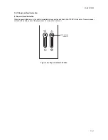
Page 42: ...aper misfeed indication When a paper misfeed occurs the printer immediately stops printing and flash the ATTENTION indicator To remove paper misfeed in the printer pull out the paper cassette or open the rear cover Figure 1 5 1 Paper misfeed indication ATTENTION indicator ...

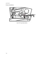
Page 43: ...2GL 2FV 2FW 1 5 2 2 Paper misfeed detection Figure 1 5 2 Paper misfeed detection Exit sensor Registration sensor ...

Page 44: ...1 0 0 1 1 1 1 0 0 0 0 1 1 1 1 1 0 0 0 1 1 1 0 0 1 1 0 1 1 1 0 1 0 1 0 1 1 1 0 1 1 1 0 1 1 0 0 0 1 1 1 A0 6400 1 0 1 0 0 0 0 0 1 1 0 0 1 0 1 1 ATTENTION indicator Interval Hexadecimal Repeat Example self diagnostic code E6 F050 Self diagnostic code conversion table READY indicator Green READY ATTENTION indicator Amber ATTENTION 0 7 3 s 2 4 s 16 18 ppm printers only Remark The ATTENTION indicator me...

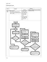
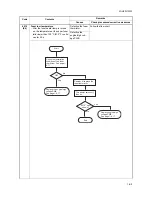
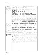
Page 45: ...of CN1 connector on the main motor Connect circuit tester to pin 5 REMOTE of YC5 connector on the engine high voltage PWB Replace engine high voltage PWB See page 1 6 17 Connect oscilloscope to pin 5 REMOTE and pin 3 MMOTRDY of CN1 connector on the main motor Print status page Replace the main motor See page 1 6 24 If not solved check or replace drive unit See page 1 6 23 24 V DC at pin 1 of CN1 c...

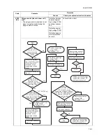
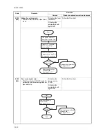
Page 46: ... Turn power switch on Turn power switch on Turn power switch off then on Turn power switch on 1417 Hz 705 µs Replace engine high voltage PWB See page 1 6 17 Replace engine high voltage PWB See page 1 6 17 Replace engine high voltage PWB See page 1 6 17 Replace laser scanner unit See page 1 6 21 Replace harness between engine high voltage PWB and laser scanner unit Replace engine high voltage PWB S...

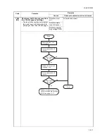
Page 47: ...illoscope to pin 3 OUTPEN of YC4 1 YC6 2 connector on the main PWB Connect oscilloscope to pin 3 OUTPEN and pin 7 of YC4 1 YC6 2 connector on the main PWB Turn power switch off then on Turn power switch off then on Replace main PWB See page 1 6 15 or 16 Replace main PWB See page 1 6 15 or 16 Replace engine high voltage PWB See page 1 6 17 Replace harness between main PWB and engine high voltage PW...

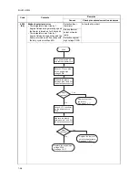
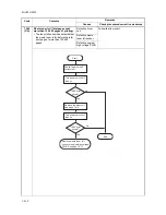
Page 48: ...switch on Turn power switch on Replace laser scanner unit See page 1 6 21 Replace main PWB See page 1 6 15 or 16 Replace main PWB See page 1 6 15 or 16 Replace engine high voltage PWB See page 1 6 17 Replace engine high voltage PWB See page 1 6 17 Replace harness between main PWB and laser scanner unit Replace harness between main PWB and laser scanner unit See page 1 6 15 or 16 Replace harness be...

Page 49: ...amp Defective engine high voltage PWB Code Contents Remarks Causes Check procedures corrective measures No No Start Yes Yes Replace the engine high voltage PWB See page 1 6 17 Replace the fuser thermistor See page 1 6 11 Replace the thermal cutout or heater lamp See page 1 6 11 Turn power switch off and remove power cord Detach YC7 connector on the engine high voltage PWB Detach YC1 connector on t...

Page 50: ...low the flow chart Defective the engine high volt age PWB Code Contents Remarks Causes Check procedures corrective measures No Start Yes Replace engine high voltage PWB See page 1 6 17 Replace the engine high voltage PWB See page 1 6 17 Check the installation condition of the fuser thermistor See page 1 6 11 Remedy or replace the fuser thermistor OK No Yes End Turn power switch off then on 6010 er...

Page 51: ...r source PWB Follow the flow chart Defective the engine high volt age PWB Code Contents Remarks Causes Check procedures corrective measures No Start Yes Replace engine high voltage PWB See page 1 6 17 Replace fuser thermistor See page 1 6 11 Turn power switch off and remove power cord Detach YC7 connector on the engine high voltage PWB Measure resistance between pins 1 and 2 of the detached connec...

Page 52: ...um unit Follow the flow chart Defective waste toner full sensor Defective engine high voltage PWB Code Contents Remarks Causes Check procedures corrective measures No No End Yes Yes Turn power switch off then on Turn power switch off then on Shake the drum unit horizontally Replace the drum unit See page 1 6 6 Replace the waste toner full sensor or engine high voltage PWB See page 1 6 17 Start 798...

Page 53: ...drum unit Follow the flow chart Defective waste toner full sensor Defective engine high voltage PWB Code Contents Remarks Causes Check procedures corrective measures No No End Yes Yes Turn power switch off then on Turn power switch off then on Shake the drum unit horizontally Replace the drum unit See page 1 6 6 Replace waste toner full sensor or engine high voltage PWB See page 1 6 17 Start 7990 ...

Page 54: ...Main PWB system error The error pertaining to the system occurred except the F0 F010 condi tion Defective main PWB Replace the main PWB See page 1 6 15 or 1 6 16 F040 E0 Main Engine communication error The communication breakdown occurred between the main PWB and the engine high voltage PWB during the predetermined period in seconds Defective engine high voltage PWB Replace the engine high voltage...

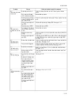
Page 55: ...ource PWB or engine high voltage PWB See page 1 6 17 2 The main motor does not operate Self diagnostic code 2000 Poor contact in the main motor connector terminals Reinsert the connector Also check for continuity within the con nector harness If none remedy or replace the harness Broken main motor gear Check visually and replace the main motor if necessary Defective main motor Replace the main mot...

Page 56: ... 17 6 The heater lamp does not turn on Broken wire in heater lamp Check for continuity across each heater lamp If none replace the heater lamp See page 1 6 11 Thermal cutout triggered Check for continuity across thermal cutout If none remove the cause and replace the thermal cutout See page 1 6 11 7 The heater lamp does not turn off Broken fuser thermistor Measure the resistance If it is Ω replace...

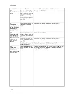
Page 57: ...n the power switch is turned on A piece of paper torn from paper is caught around reg istration sensor or exit sen sor Check and remove if any Defective registration sen sor on the engine high volt age PWB Replace the engine high voltage PWB See page 1 6 17 Defective exit sensor on the power source PWB Replace the power source PWB See page 1 6 17 13 The indicator requesting cover to be closed is d...

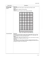
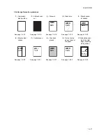
Page 58: ...18 See page 1 5 19 See page 1 5 19 See page 1 5 20 6 Black vertical streaks 7 Unsharpness 8 Gray back ground 9 Dirt on the top edge or back of the paper 10 Undulated print ing at the right edge scanning start position See page 1 5 20 See page 1 5 21 See page 1 5 21 See page 1 5 22 See page 1 5 22 ABC 123 ABC 123 ABC 123 ABC 123 ABC 123 ABC 123 This vertical line should be straight ...

Page 59: ...eplace the laser scanner unit See page 1 6 20 4 Defective main PWB Defective laser scanner unit control circuit in the main PWB See page 1 6 15 or 1 6 16 2 No image appears entirely black Causes 1 Defective main charger unit 2 Defective main charger high voltage output 3 Defective engine high voltage PWB 4 Defective main PWB Causes Check procedures corrective measures 1 Defective main charger unit...

Page 60: ...e 1 6 11 4 Defective paper specifications Paper with rugged surface or dump tends to cause dropouts Replace paper with the one that satisfies the paper specifications 5 Defective transfer roller installation The transfer roller must be supported by the bushes at the both ends Clean the bush to remove oil and debris Replace the transfer roller if necessary See page 1 6 11 6 Defective engine high vo...

Page 61: ...t See page 1 6 7 6 Black vertical streaks Causes 1 Contaminated main charger wire 2 Defective drum surface 3 Defective magnet roller in the developer unit Causes Check procedures corrective measures 1 Contaminated main charger wire Clean the main charger wire by sliding the green colored cleaning knob in and out several times 2 Defective drum surface A streak of toner remaining on drum after print...

Page 62: ...er for draft printing purpose For normal printing turn the EcoPrint mode off by using the operator panel For details refer to the operation guide 8 Gray background Causes 1 Print density setting 2 Defective drum surface potential 3 Defective main charger grid 4 Developing roller in the developer unit Causes Check procedures corrective measures 1 Print density setting The print density may be set t...

Page 63: ... the transfer roller is contaminated with toner clean the transfer roller using a vacuum cleaner or by continuously printing a low density page until the symptom has faded away 10 Undulated printing at the right edge scanning start position Causes 1 Defective laser scanner unit 2 Defective engine controller circuit in the engine high voltage PWB Causes Check procedures corrective measures 1 Defect...

Page 64: ... 4 Multiple sheets of paper are fed at one time Check if the separator pad is worn Replace the separator pad if it is worn Check if the paper is curled Change the paper 5 Paper jams Check if the paper is excessively curled Change the paper Check if the contact between the upper and lower registration rollers is correct Check visually and remedy if necessary Check if the upper and lower fuser rolle...

Page 65: ...2GL 2FV 2FW 1 5 24 This page is intentionally left blank ...

Page 66: ... PWB containing ICs with bare hands or any object prone to static charge Use only the specified parts to replace the fuser thermostat Never substitute electric wires as the printer may be seriously damaged Use the following circuit testers when measuring voltages Hioki 3200 Sanwa MD 180C Sanwa YX 360TR Beckman TECH300 Beckman DM45 Beckman 330 Capable of measuring RMS values Beckman 3030 Capable of...

Page 67: ...r and top cover Procedure 1 Open the top cover 2 Remove the right side cover Figure 1 6 1 Removing the right side cover 3 Remove the paper cassette 4 Unlatch the four latches and then remove the right cover Figure 1 6 2 Removing the right cover Right side cover Top cover Right cover Four latches cover inside ...

Page 68: ...e 1 6 3 Removing the left cover 6 Remove the one connector 7 While opening the rear cover and then remove the two screws 8 While unhooking the hooks and then remove the top cover Figure 1 6 4 Removing the top cover Three latches cover inside Left cover Left cover Hooks Hook Procedure of refitting the left cover Screw Screw Rear cover Hook Hook Connector Top cover ...

Page 69: ...4 1 6 3 Paper feeding conveying section 1 Detaching and refitting the paper feed roller Procedure 1 Remove the paper cassette 2 Remove the paper feed roller Figure 1 6 5 Removing the paper feed roller Paper feed roller ...

Page 70: ... the developer unit and drum unit See page 1 6 6 2 Remove the transfer roller from bushes Figure 1 6 6 Removing the transfer roller Transfer roller Transfer roller Bush black Spring black Transfer roller gear Bush Spring Paper passing direction Paper passing direction Bush Long Short ...

Page 71: ... example damaged due to scratches the waste toner reservoir is full per form the drum unit optimization procedure See page 1 6 7 Procedure 1 Open the top cover 2 Remove the developer unit with toner con tainer Figure 1 6 7 Removing the developer unit 3 Remove the drum unit Figure 1 6 8 Removing the drum unit Developer unit Top cover Drum unit ...

Page 72: ...hout installing the developer unit 7 Turn power on The LED indicators dis played developer unit missing error indica tion READY indicator Off ATTENTION indicator Lit 8 Press the CANCEL key 5 seconds or more 9 Drum unit optimization is complete when let ting go off of the CANCEL key Completion Printer starts idling for 10 seconds Idling can be checked by rotation of FD roller Failure Printer does n...

Page 73: ...rger unit Procedure 1 Remove the drum unit See page 1 6 6 2 While pushing on the main charger terminal slide the main charger unit 3 Remove the main charger unit by lifting it Figure 1 6 11 Main charger unit Drum unit Main charger terminal Main charger unit ...

Page 74: ...e two connectors 3 Remove the wire from two clamps Figure 1 6 12 4 Pull out the rear cover axis with spring from the axis hole on side 5 Pull out the rear cover axis from the axis hole on side and remove the rear cover and the spring Figure 1 6 13 Connector Clamp Clamp Wire Connector Spring Spring Rear cover Axis Axis hole Axis Axis hole ...

Page 75: ...the two screws and then remove the fuser unit Figure 1 6 14 7 Remove the two screws and then separate the upper fuser frame and lower fuser frame Figure 1 6 15 Fuser unit Screw Screw Screw Screw Upper fuser frame Lower fuser frame ...

Page 76: ...oller Procedure 1 Remove the fuser unit See page 1 6 9 2 Remove the two screws and terminal 3 Remove the heater lamp Seat the heater lamp aligning its wattage mark and welding mark faced with the cor rect direction and side Figure 1 6 16 Screw Heat gear Welding mark Screw Terminal Heater lamp Wattage mark Heater lamp ...

Page 77: ...uide 5 Remove the heat R bush heat L bush and heat gear from the heat roller Figure 1 6 17 6 Remove the one screw and then remove the fuser thermistor Figure 1 6 18 Heat roller Upper fuser guide Heat roller Heat roller Heat L bush Heat L bush Heat R bush Heat R bush Heat gear Fuser thermistor Screw ...

Page 78: ...2GL 2FV 2FW 1 6 13 7 Remove the two screws nuts plate cord and terminal 8 Remove the thermal cutout Figure 1 6 19 Screw Plate cord Terminal Thermal cutout Screw Nut Nut ...

Page 79: ...2GL 2FV 2FW 1 6 14 9 Remove the press roller from the bushes Figure 1 6 20 Removing the press roller Press roller Lower fuser frame Bush Bush ...

Page 80: ...nter Procedure 1 Remove the right cover See page 1 6 2 2 Remove the two connectors from main PWB 3 Remove one screw from the USB interface connector 4 Remove the three screws and then remove the main PWB Figure 1 6 21 Main PWB USB interface connector Screw Screw Screw Screw Connectors ...

Page 81: ...emove the CF guide 3 Remove the two connectors from main PWB 4 Remove three screws from the USB inter face connector and parallel interface con nector 5 Remove the four screws and then remove the main PWB with controller box Figure 1 6 22 Screws Screws Screws Connectors Controller box Main PWB Parallel interface connector USB interface connector Screw CF guide ...

Page 82: ... cassette 3 Remove the outer covers See page 1 6 2 4 Remove the six connectors When seating the engine high voltage PWB ensure that the developer bias terminal spring is correctly in contact with the devel oping bias terminal TB1 on the engine high voltage PWB Figure 1 6 23 Connector Connectors Developing bias terminal spring Engine high voltage PWB Developing bias terminal TB1 ...

Page 83: ...23 Figure 1 6 24 7 Turn the printer bottom side up 8 Remove the five screws and then remove the bottom frame plate with PWBs behind the plate Figure 1 6 25 Connectors Main PWB 16 18 ppm printers Drive unit Main PWB 16 ppm GDI printer Connectors Bottom frame plate Transfer bias terminal Screws Screws ...

Page 84: ...high voltage PWB and power source PWB 13 Check or replace the engine high voltage PWB or power source PWB and then refit all the removed parts To replace the engine high voltage PWB remove the EEPROM U2 from the old engine high voltage PWB and mount it to the new engine high voltage PWB Figure 1 6 26 Screws Screw Screw Screw Terminal Power source PWB Bottom frame plate Engine high voltage PWB Conn...

Page 85: ...2FW 1 6 20 1 6 7 Others 1 Detaching and refitting the laser scanner unit Procedure 1 Remove the outer covers See page 1 6 2 2 Remove the two screws and then remove the LSU lid Figure 1 6 27 Screw Screw LSU lid ...

Page 86: ...2GL 2FV 2FW 1 6 21 3 Remove the three screws 4 Remove the two connectors and then remove the laser scanner unit Figure 1 6 28 Screw Connectors Screw Screw Laser scanner unit ...

Page 87: ...emove the laser scanner unit See page 1 6 20 2 Remove the one connector 3 Remove the wire from two clamps Figure 1 6 29 4 Remove the wire form clamp 5 Remove the sheet eraser 6 Remove the eraser lamp PWB Figure 1 6 30 Connector Wire Clamps Eraser lamp PWB Sheet eraser Clamp Wire ...

Page 88: ... then remove the two grounding plates 4 Remove the two stoppers and then remove the two clutches Figure 1 6 31 5 Remove the one screw and then remove the CF guide 6 Remove the three screws and then remove the drive unit Figure 1 6 32 Screw Clutch Clutch black Stopper Stopper Grounding plate Grounding plate Screw Connectors Screw Screw Screw Drive unit Screw CF guide ...

Page 89: ...ng and refitting the main motor Procedure 1 Remove the right cover See page 1 6 2 2 Remove the one connector from main motor 3 Remove the four screws and then remove the main motor Figure 1 6 33 Screws Screws Connector Main motor ...

Page 90: ...in controller 4 Facsimile 5 NIC 6 Operation panel massage language 7 Panel Firmware description supplement Product code 2FV 16 ppm printer 2FW 18 ppm printer Software ID Firmware file name example For 16 18 ppm printers Build number 0 Normal E Corrective Pause under bar Pause period Compression Destination S2FV_1000001021 cmp Version up history Firmware description 1 Engine controller ...

Page 91: ...rface The printer system can automatically rec ognize whether the data to be overwritten is for controller firmware CAUTION Downloading the firmware takes several minutes Do not turn power off during downloading 1 Turn printer and PC power off 2 Connect the parallel printer cable between the PC and the printer Figure 1 7 2 Parallel interface connector Parallel cable PC ...

Page 92: ...ring downloading When LED indication status is displayed to indicate down loading is finished turn printer power off then on If downloading fails the printer indicates an error display using the LED indicators See table below LED indication status 9 Confirm that LED indication status is displayed after warm up 10 Print a status page See page 1 4 3 11 Check that the status page shows the updated fi...

Page 93: ... power off during downloading If downloading is interrupted by an accidental power failure etc the main PWB may have to be replaced Do not download the system firmware and engine firmware at one time Store the either firmware in a memory card and download one by one 1 Turn power switch off 2 Remove the right side cover 3 Insert the memory card in the printer s mem ory card slot Figure 1 7 3 Right ...

Page 94: ... using the LED indicators See table below LED indication status Table 1 7 2 6 Turn power off 7 Remove the memory card and then refit the right side cover 8 Turn power on again Check the printer gets ready 9 Print a status page See page 1 4 3 10 Check that the status page shows the updated firmware version Receiving data Supervisor mode Ready Downloading complete Off Off Lit Lit LED Indicator expla...

Page 95: ...2GL 2FV 2FW 1 7 6 This page is intentionally left blank ...

Page 96: ... processing 1 Paper feed section The figure below shows the components in the paper feeding conveying section and the paths through which the paper travels The sensors clutches motor etc are described in the following pages Figure 2 1 1 Paper feeding conveying section 1 Feed roller 2 Feed pulley 3 Lower registration roller 4 Upper registration roller 5 Registration sensor Actuator 6 Base plate 7 C...

Page 97: ...4V3 FEDSOLON 24V3 GND MMOTRDY MOTCLK REMOTE GND FEDDOLON REGSOLON 24V3 Feed clutch Main motor CN1 1 CN1 2 CN1 3 CN1 4 CN1 5 Engine high voltage PWB Registration sensor Paper sensor YC3 13 YC3 8 YC3 7 YC3 6 YC5 1 YC5 2 YC5 3 YC5 4 YC5 5 Connect PWB YC401 8 YC402 1 YC403 1 YC403 2 YC402 2 YC401 3 YC401 2 YC401 1 ...

Page 98: ...a screwdriver etc resulting in a print quality problem Also finger prints can cause deterioration of the OPC layer therefore the drum in the drum unit must be handled with care Substances like water alcohol organic solvent etc should be strictly avoided As with all other OPC drums the exposure to a strong light source for a prolonged period can cause a print quality prob lem The limit is approxima...

Page 99: ...contaminated by oxi dization after a long run Cleaning the charging wire prevents print quality problems such as black streaks Figure 2 1 4 Main charger unit Figure 2 1 5 Drum unit and main charger unit block diagram Drum 1 Main charger shield 2 Main charger wire 3 Main charger grid 4 Main charger wire cleaner Main charger wire Main charger output Grid Shield Drum Engine high voltage PWB Zener PWB...

Page 100: ...length beam is dispersed as the polygon motor revolves 27959 rpm to reflect the laser beam over the drum Various lenses and mirror are housed in the laser scanner unit adjust the diameter of the laser beam and focalize it at the drum surface Figure 2 1 6 Laser scanner unit Laser beam Drum 1 Laser scanner unit 2 MID frame 3 LSU lid 4 LSU shutter 5 LSU mirror 6 Polygon motor mirror ...

Page 101: ...a lens equalizes focusing distortion on the far ends of the drum 5 Sensor mirror Bends the very first shot of a laser scan towards the pin photo diode sen sor 6 Pin photo diode sensor When shone by the sensor mirror above this pin photo diode sensor generates a trigger signal for the engine controller to start activating the paper feeding system 7 LSU mirror Diverts the laser beam vertically onto ...

Page 102: ...is applied with the AC weighted positive DC power source Toner on the developing roller is given a positive charge The positively charged toner is then attracted to the areas of the drum which was exposed to the laser light The gap between the drum and the developing roller is 0 32 mm The non exposed areas of the drum repel the positively charged toner as these areas maintain the positive charge T...

Page 103: ...2GL 2FV 2FW 2 1 8 Figure 2 1 9 Developing section block diagram Developing roller Developing bias output Engine high voltage PWB 350 5 V DC AC TB1 ...

Page 104: ...e transfer roller is negatively biased so that the positively charged toner is attracted onto the paper while it is pinched by the drum and the transfer roller Figure 2 1 10 Transfer section Figure 2 1 11 Transfer section block diagram Transfer roller Transfer roller Transfer bias output 2 3 kV 9 µA 2 6 kV 12 µA Engine high voltage PWB J1 J2 J3 Switches output depending on media type and media siz...

Page 105: ...aned it then must be cleaned to the electrically neutral state This is necessary to erase any residual positive charge ready to accept the uniform charge for the next print process The residual charge is canceled by exposing the drum to the light emitted from the eraser lamp PWB This lowers the electrical conductivity of the drum sur face making the residual charge on the drum surface escape to th...

Page 106: ...er has four claws separators which are continuously in contact with its surface These claws separators prevent the paper on which toner has been fused from being wound around the heat roller causing paper jam The press roller is made of the heat resistant silicon rubber This roller is used to strongly press the paper towards the heat roller by means of coil springs The temperature of the heat roll...

Page 107: ...re 2 1 15 Fuser section block diagram Fuser thermistor Heater lamp N L THERM 5V HEATN SLEEP ZCROSS Thermal cutout Power source PWB Fuser unit CN1 1 CN1 3 YC2 6 YC2 7 YC2 9 Engine high voltage PWB YC1 6 YC1 7 YC1 9 YC7 1 YC7 2 ...

Page 108: ... the fuser unit turns on the exit sensor which is driven by the fuser actuator in the fuser unit and is led by the guide comprised of the rear cover and the frame finally reaching the FD roller The paper is delivered to the output tray by the rotation of the FD roller Figure 2 1 16 Paper exit section 1 Output tray 2 FD pulley 3 FD roller 4 Rear cover 5 Fuser actuator 6 Exit sensor actuator ...

Page 109: ...2GL 2FV 2FW 2 1 14 Figure 2 1 17 Paper exit section block diagram Power source PWB Fuser unit Exit sensor YC2 8 Engine high voltage PWB YC1 8 EXITN ...

Page 110: ...cates the LED indicators and controls key inputs 7 Eraser lamp PWB Eliminates the residual electrostatic charge on the drum 8 Zener PWB Adjusts the main charger grid electrostatic potential 9 Registration sensor Detects the timing of primary feeding and paper jam 10 Paper sensor Detects paper in the paper cassette 11 Exit sensor Detects paper jam in the fuser unit and paper exit section 12 Toner e...

Page 111: ...per feed 21 Registration clutch Controls the primary paper feed 22 AC inlet Connects the AC power source 23 Thermal cutout Shuts off the power source to the heater lamp when the heat roller reaches extremely high temperature 24 Heater lamp Energizes the heat roller ...

Page 112: ...t to the engine high voltage PWB The zero cross signal detection circuit detects the 0 V point zero cross of the AC wave form and outputs to the engine high voltage circuit and the engine high voltage PWB outputs the heater lamp ON signal HEATN to the heater lamp control circuit based on the timing of zero cross signal ZCROSS and controls the AC power loading to the heater lamp D10 to 13 D31 D32 C...

Page 113: ...0 V AC Power supply for heater lamp On Off YC2 1 5V O 5 V DC 5 V DC power output Connected to the engine high voltage PWB 2 5V O 5 V DC 5 V DC power output 3 GND Ground 4 GND Ground 5 24V I 24 V DC 24 V DC power input via interlock switch 6 HEATN I 0 24 V DC Heater lamp On Off 7 SLEEP I 0 5 V DC Sleep mode On Off 8 EXITIN O 0 5 V DC Exit sensor On Off 9 ZCROSS O 0 5 V DC pulse Zero cross signal 10...

Page 114: ...3 TNFULL TONER ERASERON FANH FANL MMOTON MOTCLK MMOTRDY ZCROSS SLEEPN HEATN HEAT THERM EXITPAP ILOCK ILOCK Main charger 24V2 Exit sensor 5V Developing bias Transfer bias 24V2 24V1 24V1 Cooling fan motor Main motor Main PWB Fuser thermistor Power source PWB PLGON PLGRDY Interlock switch FPSW Engine high voltage PWB FPLED1 FPLED2 BUZZ Buzzer REGSOLON FEDSOLON PLGCLK OUTPEN Operation panel PWB Connec...

Page 115: ...12 FPSW I Analog 5 V DC 3 160 to 3 394 V DC 2 544 to 2 798 V DC 1 947 to 2 193 V DC GO key SW1 and CANCEL key SW2 input SW1 Off SW2 Off SW1 Off SW2 On SW1 On SW2 Off SW1 On SW2 On 13 GND Ground YC4 1 RESETN O 0 5 V DC Reset signal Connected to the main PWB 2 EGIRN O 0 5 V DC Engine interrupt signal 3 SDIR O 0 5 V DC Communication direction change signal 4 SBSY O 0 5 V DC Engine busy signal 5 PDMAS...

Page 116: ...p PWB On Off YC9 1 24V1 O 24 V DC 24 V DC power output Connected to the cool ing fan motor 2 FAN O 0 12 24 V DC Cooling fan motor Full speed Half speed Off YC10 1 5V O 5 V DC 5 V DC power output Connected to the toner empty sen sor 2 TONER I 0 5 V DC Toner empty Not 3 GND Ground Connector Pin No Signal I O Voltage Description ...

Page 117: ...ed with the process and paper feeding conveying mechanism that the engine high voltage PWB controls SYSCK X2 OSC video 85 761 MHz VOSC X1 U2 YC2 YC3 YC4 Engine I F APC I F USB I F USBDP USBDN 48 000 MHz OSC USB System RESIN ESTSN PDMSKN VIDEON VDCLK ECPRDYN ERSTN P04 P05 06 ESBSYN VBDN VXC EINTN P07 PLGCLK SBSY SDIR EGIRN ECCLKN ECMDN OUTPEN VDATA VDFONSPL PDN 5V1 3 3 V regulator 3 3V1 U7 SDRAM ad...

Page 118: ...1284DIR NSELIN NSTROBE NAUTOFD NINIT NACK PERROR SELECT FAULT BUSY USBDN PDATA7 0 PNSELIN PNSTROBE PNAUTOFD PNINIT PNACK PPERROR PSELECT PFAULT PBUSY 48 000 MHz OSC USB System Power source 5V SGND SCKN SO PLGCLK SBSY SI SDIR EGIRN PDMASKN RESIN OUTPEN VDATA VDFONSPL PDN 5V1 SDD31 0 SDRAM data bus 3 3 V regulator 3 3V1 U07 SDD31 16 SDCLK SDRAM DIMM slot SDCLK IICSCL SDA12 0 SDA12 0 EBD31 0 EBIU dat...

Page 119: ...F USB I F USBDP P1284DIR NSELIN NSTROBE NAUTOFD NINIT NACK PERROR SELECT FAULT BUSY USBDN PDATA7 0 PNSELIN PNSTROBE PNAUTOFD PNINIT PNACK PPERROR PSELECT PFAULT PBUSY 48 000 MHz OSC USB System Power source 5V SGND SCKN SO PLGCLK SBSY SI SDIR EGIRN PDMASKN RESIN OUTPEN VDATA VDFONSPL PDN 5V1 SDD31 0 SDRAM data bus 3 3 V regulator 3 3V1 U07 SDD31 16 SDCLK SDRAM DIMM slot SDCLK IICSCL SDA12 0 SDA12 0...

Page 120: ...bias Developing bias Registration clutch Feed clutch Laser scanner unit OUTPEN Laser scanner unit PDMASK 0 ms 0 0 100 200 330 200 921 1054 1154 1154 1154 1645 1397 2916 3705 3879 3917 3917 4179 4600 4732 4832 4179 4136 4832 4832 5076 5324 5433 6595 7384 7596 7596 7858 12 s 11 10 9 8 7 6 5 4 3 2 1 1 0 7815 7858 9112 9448 10708 10708 10708 11208 10708 8467 8185 Drum speed 118 5 mm s Paper feeding sp...

Page 121: ...2 4676 4924 5433 6195 6984 7196 7196 7458 7415 7458 8712 9048 10308 10308 10308 10808 10308 8065 7785 Main motor Exit sensor Registration sensor Main charger Laser scanner unit PLGON Eraser lamp Transfer bias Developing bias Registration clutch Feed clutch Laser scanner unit OUTPEN Laser scanner unit PDMASK 12 s 11 10 9 8 7 6 5 4 3 2 1 1 0 Drum speed 118 5 mm s Paper feeding speed 147 0 mm s Print...

Page 122: ...97 4197 Main motor Exit sensor Registration sensor Main charger Laser scanner unit PLGON Eraser lamp Transfer bias Developing bias Registration clutch Feed clutch Laser scanner unit OUTPEN Laser scanner unit PDMASK 9 s 8 7 6 5 4 3 2 1 1 0 Drum speed 118 5 mm s NOTE A represents the period of time of waiting for controlling the heater lamp The period of 3 5 s should be allowed for media sizes small...

Page 123: ...ration panel PWB Main motor Laser scanner unit Polygon motor Laser diode Pin photo diode sensor 24V3 GND MMOTRDY MOTCLK REMOTE 1 2 3 4 5 1 2 3 4 5 5 4 3 2 1 13 12 11 10 9 8 7 6 5 4 3 2 1 1 2 3 4 5 6 7 8 9 10 11 12 1 2 3 4 5 6 7 8 9 10 11 12 1 2 3 4 5 6 7 8 9 10 11 12 1 2 3 4 1 2 3 4 GND FPSW FPLED1 FPLED2 BUZ FEDDOLON REGSOLON 24V3 1 2 1 2 1 2 3 1 2 3 1 2 3 1 2 3 RESETN EGIRN SDIR SBSY PDMASKN EGS...

Page 124: ... defects gauge First occurrence of defect 24 mm Upper registration roller 38 mm Lower registration roller 63 mm Heat roller Press roller Fuser unit 47 2 mm Developing roller Developer unit 94 mm Drum Drum unit 48 mm Transfer roller ...

Page 125: ...2GL 2FV 2FW 2 4 6 This page is intentionally left blank ...

Page 126: ......

Reviews: