2GL/2FV/2FW
1-6-19
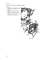
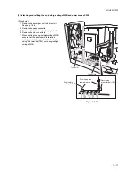
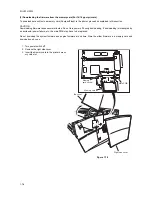
9. Remove the one screw and terminal from
the bottom frame plate.
* When securing the grounding terminal, hook
the grounding wire to the projection.
10. Remove the three screws from power
source PWB.
11. Remove four screws from the engine/high
voltage PWB.
12. Separate the engine/high voltage PWB and
power source PWB.
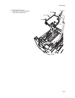
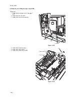
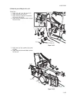
13. Check or replace the engine/high voltage
PWB or power source PWB and then refit all
the removed parts.
* To replace the engine/high voltage PWB,
remove the EEPROM (U2) from the old
engine/high voltage PWB and mount it to
the new engine/high voltage PWB.
Figure 1-6-26
Screws
Screw
Screw
Screw
Terminal
Power source PWB
Bottom frame plate
Engine/high
voltage PWB
Connectors
Screws
Screw
EEPROM
Socket
Terminal
Screw
Projection
Power source PWB
Grounding wire
Summary of Contents for LP 3118
Page 1: ...Service Manual Printer LP 3118 22 02 2005 ...
Page 2: ...Service Manual Printer LP 4118 22 02 2005 ...
Page 7: ...This page is intentionally left blank ...
Page 19: ...2GL 2FV 2FW 1 1 10 This page is intentionally left blank ...
Page 21: ...2GL 2FV 2FW 1 2 2 This page is intentionally left blank ...
Page 29: ...2GL 2FV 2FW 1 3 8 This page is intentionally left blank ...
Page 41: ...2GL 2FV 2FW 1 4 12 This page is intentionally left blank ...
Page 65: ...2GL 2FV 2FW 1 5 24 This page is intentionally left blank ...
Page 95: ...2GL 2FV 2FW 1 7 6 This page is intentionally left blank ...
Page 125: ...2GL 2FV 2FW 2 4 6 This page is intentionally left blank ...
Page 126: ......

