3S3
2-3-1
2-3 Operation of the PWBs
2-3-1
Main PWB
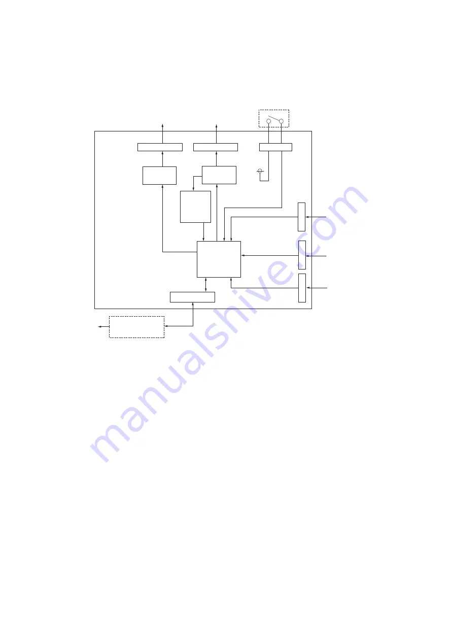
The diagram below shows the main PWB and the components of the bulk paper feeder.
Figure 2-3-1Main PWB block diagram
Tray
elevation
motor
Cover
interlock
switch
Tray top
position
sensor
Paper
feed
sensor
Tray
bottom
position
sensor
Paper feed
motor
Transistor
circuit
YC3
YC1
YC7
YC5
OP3.3V
YC2
CPU
Printer base
Printer
Motor
driver
Over
current
detection
circuit
YC4
YC6
Summary of Contents for PF-3100
Page 1: ...Service Manual Paper Feeder PF 3100 First Edition Date 17 10 2016 3S3SM060 ...
Page 2: ...Service Manual Paper Feeder PF 3100 First Edition Date 17 10 2016 3S3SM060 ...
Page 4: ...Revision history Revision Date pages Revised contents ...
Page 5: ...This page is intentionally left blank ...
Page 11: ...This page is intentionally left blank ...
Page 13: ...2 4 Appendixes 2 4 1 Wiring diagram 2 4 1 ...
Page 14: ...This page is intentionally left blank ...
Page 15: ......
Page 21: ...3S3 1 1 6 This page is intentionally left blank ...
Page 43: ...3S3 1 3 12 This page is intentionally left blank ...
Page 51: ...3S3 2 1 4 This page is intentionally left blank ...
Page 57: ...3S3 2 3 4 This page is intentionally left blank ...


