95-8401
12
2.1
9. Check the sensor wiring to ensure proper connec-
tions, then pour the conduit seals and allow them
to dry (if conduit is being used).
10. Place the cover back on the junction box.
CONTROLLER WIRING
NOTE
The controller contains semiconductor devices
that are susceptible to damage by electrostatic
discharge. An electrostatic charge can build
up on the skin and discharge when an object is
touched. Therefore, use caution when handling,
taking care not to touch the terminals or electronic
components. For more information on proper
handling, refer to Service Memo form 75-1005.
Field Wiring Connector
The controller is furnished with a field wiring
connector backplate that incorporates pressure type
screw terminals for connecting the external wiring
and a circuit board edge connector for attaching
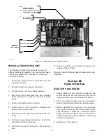
to the controller. The use of a mounting rack is
recommended for mounting the controller. The
backplate is attached to the back of the rack to allow
easy removal of the controller without disturbing the
wiring. See Figures 9 and 10.
The controller is designed for installation in a non-haz-
ardous area.
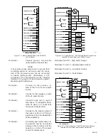
Figure 11 shows the terminal configuration for the
R8471B H
2
S Controller.
Terminals 1 and 2 – 4 to 20 ma dc output.
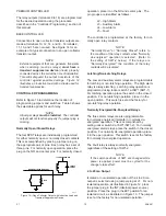
Non-Isolated Current Output
-
If the 4 to 20 ma current loop
is to be non-isolated, wire the
current loop as shown in Figure
12. Note that terminal 2 is not
used with a non-isolated current
loop. Program the controller
for a non-isolated current loop
as described in the “Controller
Programming” section of this
manual.
Isolated Current Output
- If an
isolated current loop is desired,
wire the current loop as shown
in Figure 13 and program the
controller for an isolated cur-
rent loop as described in the
“Controller Programming” sec-
tion of this manual. Note that
this wiring scheme requires an
external power source for the
isolated current output.
CURRENT OUTPUT
CHASSIS GROUND
POWER
SENSOR
EXTERNAL RESET
HIGH ALARM
HIGH ALARM / OC
AUX. ALARM
AUX. ALARM / OC
LOW ALARM
LOW ALARM / OC
FAULT
FAULT / OC
1
3
4
5
6
7
8
9
10
11
12
13
14
15
16
–
+
+
–
+
–
18 TO 32
VDC
POWER
SIGNAL
24
VDC
*
+
–
C7064C
SENSOR
2
A1704
R8471B CONTROLLER
BLK
RED
GREEN
+
–
MTL 787S
OR
MTL 788
OC = OPEN COLLECTOR OUTPUT
(BASE MODEL ONLY)
*
WHEN USING AN I. S. BARRIER,
INPUT VOLTAGE MUST BE 23 TO 26.6 VDC.
Figure 8—R8471B Controller and C7064C Sensor
Used with I.S. Barrier
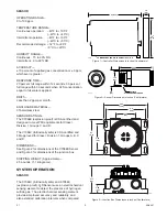
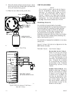
SENSOR
GROUND
BLK (–) TO TERMINAL 7
RED (+) TO TERMINAL 6
WIRING TO CONTROLLER
GROUND JUNCTION BOX
ACCORDING TO LOCAL CODES
B1528
RED
BLK
GRN
=
=
=
+
–
GROUND
FIBER FILLER
SEALING COMPOUIND
Figure 7—Sensor Wiring

