95-8401
4
2.1
to ordinary solid state type sensors. A significant
property of the sensing element is its highly
specific response to H
2
S. Since many commonly
encountered gases have little if any effect on the
electrical response of the sensor, false indications
caused by the presence of these gases are greatly
reduced. In addition, high concentrations of H
2
S do
not adversely affect the sensor.
The sensor housing contains the transmitter circuitry
for generating a linear 4 to 20 milliampere dc output
signal, corresponding to levels of H
2
S from 0 to full
scale.
The sensor uses a hydrophobic filter to protect the
electrochemical sensing element from contamination
by dirt and moisture. Unlike metal filters that
significantly restrict the passage of H
2
S gas to the
sensing element when the surface is coated with
water, the hydrophobic filter sheds water and will not
inhibit the flow of H
2
S gas to the sensing element.
As with any filter, the hydrophobic filter must be kept
free of contaminants to allow H
2
S gas to reach the
sensing element.
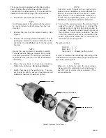
The hydrophobic filter and electrochemical sensing
element can be replaced quickly and conveniently in
the field.
NOTE
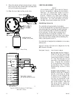
If an intrinsically safe sensor is used with the
R8471B, it must be powered through an approved
barrier in order to maintain its intrinsically safe
rating.
Sensor Cross Sensitivity
Table 2 shows the response of a typical
electrochemical H
2
S sensor when exposed to
100 ppm concentrations of various commonly
encountered substances. Note that 100 ppm
concentrations of some substances are not normally
present in most applications involving H
2
S detection
systems.
OPTIONAL TRANSMITTERS
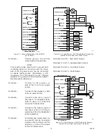
The sensor contains the transmitter circuitry for
generating a 4 to 20 ma signal, eliminating the
need for a separate transmitter. If the application
requires calibration at the sensor location or various
other special transmitter features such as relay
contacts or visible annunciators, a variety of Det-
Tronics transmitters are available for use with either
electrochemical or solid state H
2
S sensors. Refer to
the “Ordering Information” section of this manual for
more information.
CONTROLLER
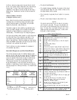
Faceplate Description
The controller faceplate provides LEDs for
identifying status conditions, a digital display and
bar graph display for indicating the sensor input,
and pushbuttons for programming, calibrating and
resetting the system. See Figure 4 for the location of
indicators and pushbuttons.
1.
Digital Display
– The digital display provides a
continuous reading (in ppm) of the sensor input
in both the Normal and Calibrate modes. In the
event of a fault, it identifi es the nature of the fault
using an alpha-numeric code. In other operat-
ing modes it shows the alarm setpoints and pro-
grammed calibration gas concentration. A nega-
tive zero drift condition is indicated by a minus
(–) sign in the left hand digit. Since this display
is always lit, it also functions as a power indicator
(except during the power-up time delay, when the
FAULT LED is on and the digital display is off).
NOTE
In the event of an over-range condition, the digital
display flashes and the highest reading latches on
until reset. The user must exercise caution if an
over-range reading is indicated, since a dangerous
condition could exist. The hazardous area should
be checked with a portable detection instrument to
determine the actual level of H
2
S gas present.
2.
Bar Graph Display
– The 20 segment bar graph
display provides a reading of sensor input in
increments of 5% of full scale.
3.
High Alarm LED
– Flashes in response to a sen-
sor signal that exceeds the high setpoint.
4.
Auxiliary Alarm LED
– Flashes in response to a
sensor signal that exceeds the auxiliary setpoint.
5.
Low Alarm LED
– Flashes in response to a sen-
sor signal that exceeds the low setpoint.
Table 2—Cross Sensitivity of Electrochemical Sensor to
100 ppm Concentrations
0 ppm
<1 ppm
<15 ppm <–30 ppm –20 ppm
HCN
CO
SO2 NO2 Cl2
C2H4 NO
H2
HCl

