background image


2 / 8 


P/N 3101999-ML • REV 1.0 • ISS 11APR12 

• 

When using a Model 449 electrical box, discard the gasket 
that is shipped with the box. 

• 

When using a trim skirt or a surface mount application, 
use the gasket that comes with the WG4 unit.  

— or — 

For flush mount applications on a flat surface, use the 
WG4GSKT gasket accessory.  

To install the horn: 

1.  Remove the cover from the appliance by first removing the 

six cover screws. See Figure 2, item 1. 

2.  Position the appropriate gasket over the backplate, 

ensuring that the wire slot and other holes line up properly. 
Remove the protective backing from the gasket surface 
and carefully apply the gasket to the WG4, with the 
adhesive side towards the appliance. Press the gasket 
firmly against the back surface of the appliance so that the 
gasket seats properly.  

3.  Place the optional trim skirt over the electrical box, if 

desired. See Figure 2, items 5 and 6. Also see 
“Specifications” on page 3 for a list of compatible boxes. 

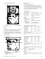
4.  Feed the field wiring through the wire slots on the gasket 

and the backplate. See Figure 2, item 3 and Figure 3, 
item 1.  

5.  Align the appliance and trim skirt (if applicable), and then 

secure the backplate to the electrical box with the supplied 
screws. Check the assembly to ensure that it is securely 
mounted. 

6.  Set the horn volume. 

The default horn volume setting is high. To set the horn to 
low volume, cut jumper JP3. See Figure 3, item 2.   

7.  Set the horn pattern. 

The default horn pattern is a 3-3 temporal output. To use a 
continuous horn pattern, cut jumper JP1. See Figure 3, 
item 3.   

8.  Connect the horn terminals appropriately to the signal 

circuit field wiring. You must observe polarity for the unit to 
function properly. See “Wiring” on page 3. 

9.  Position the cover over the backplate and secure with the 

six cover screws.  

10.  Test the unit for proper operation. 

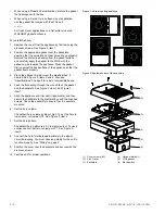
Figure 1: Horn mounting positions 


Figure 2: Exploded view of the assembly  

(1)

(2)

(3)

(4)

(5)

(6)


(1)  Cover screws (6X) 
(2) Front 

cover 

(3) Backplate 

(4)  Optional trim skirt 
(5) WG4 

gasket 

(6) Electrical 

box 

Summary of Contents for Edwards Genesis WG4 Series

Page 1: ...orn or horn strobe WG4RTS 1 Outdoor rated surface skirt red for Genesis WG4 horn or horn strobe WG4GSKT 2 Appliance replacement gasket flush mount 1 The trim skirt is outdoor rated when used with the Model 449 electrical box 2 Not compatible with the trim skirts To synchronize horn operation you must install a separate synchronization source See Table 3 When connecting the horn to a listed control...

Page 2: ... Specifications on page 3 for a list of compatible boxes 4 Feed the field wiring through the wire slots on the gasket and the backplate See Figure 2 item 3 and Figure 3 item 1 5 Align the appliance and trim skirt if applicable and then secure the backplate to the electrical box with the supplied screws Check the assembly to ensure that it is securely mounted 6 Set the horn volume The default horn ...

Page 3: ...imensions W H D 5 6 8 5 1 4 in 142 216 36 mm Sound level output See Table 4 Table 5 Table 6 and Table 7 Horn tone 3 2 kHz Wire size 12 to 18 AWG 0 75 to 2 50 mm Compatible electrical box Outdoor Indoor Model 449 4 in square by 1 5 in deep box Operating environment Temperature Relative humidity 40 to 151 F 40 to 66 C 0 to 95 noncondensing Table 4 Sound pressure level dBA per UL 464 Volume Setting 1...

Page 4: ...nd ou sur un mur Voir Table 1 pour une liste des modèles et Table 2 pour une liste des accessoires Pour les applications à montage en surface monter le WG4 sur un boîtier électrique Model 449 à l aide du joint livré avec l appareil Pour les applications à montage encastré où la surface de montage est alignée avec la surface du mur ou du plafond utiliser le nécessaire de joint WG4GSKT Remarque un b...

Page 5: ...ner le joint approprié sur la platine arrière en vérifiant que la fente de guidage des câbles et les autres orifices s alignent correctement Retirer le revêtement de protection de la surface du joint et appliquer précautionneusement le joint sur le WG4 avec le côté adhésif orienté vers l appareil L appuyer fermement contre la surface arrière de l appareil pour le positionner correctement 3 Mettre ...

Page 6: ...te de guidage des câbles et des cavaliers JP3 1 2 3 JP1 1 Fente de guidage des câbles 2 Cavalier du volume de l avertisseur sonore JP3 3 Cavalier du motif de l avertisseur sonore JP1 Câblage Voir Figure 4 Raccorder tous les fils conformément aux codes de l électricité locaux et aux exigences locales pertinentes Attention risque pour le dispositif Pour éviter d endommager le dispositif vérifier que...

Page 7: ...veau de pression sonore dBA selon UL 464 Réglage du volume 16 V 24 V 33 V Continu élevé 89 7 94 7 97 4 Continu faible 85 4 89 5 92 5 Temporel élevé 84 2 90 5 93 5 Temporel faible 81 7 85 4 88 1 dBA décibels pondérés A UL 464 niveau de sortie sonore mesuré dans une salle réverbérante à 3 05 m 10 pi Tableau 5 Niveau de pression sonore dBA selon CAN ULC S525 Réglage du volume 16 V 24 V 33 V Continu é...

Page 8: ...la partie 15 des règles FCC Son fonctionnement est soumis aux deux conditions suivantes 1 ce dispositif ne doit pas causer d interférences nuisibles et 2 il doit accepter toutes les interférences reçues y compris celles qui sont susceptibles d entraîner un fonctionnement indésirable Conformité ICES Cet appareil numérique de classe B est conforme à la norme canadienne ICES 003 Classe de service Int...

Reviews: