background image

UniFlame User Manual 

Unitized Detector Head & Amplifier 

Publication 372000-48 Rev. H 

Summary of Contents for FORNEY UniFlame

Page 1: ...UniFlame User Manual Unitized Detector Head Amplifier Publication 372000 48 Rev H ...

Page 2: ...red and sold under a contract containing limitations of manufacturer s liability for negligence and disclaimers of certain warranties Installation or use of the equipment described in this manual constitutes an acceptance by the installer and user of those limitations and disclaimers Copies of the contract may be obtained through any office of the manufacturer Copyright 2009 Forney Corporation ...

Page 3: ... by Forney and accomplished under Forney supervision PROPRIETARY NOTICE The contents of this publication are proprietary data of Forney Corporation Reproduction or use of any part of the publication for purposes other than the support of the equipment for which it is published is permissible only if expressly authorized in writing by Forney The original source of this publication is Forney Corpora...

Page 4: ...ring Harness Assembly Layout 11 SECTION 4 Remote Communications 12 4 1 Remote File Selection 13 SECTION 5 Programming UNIFLAME Series Detectors 14 5 1 Keypad Display 14 5 2 UNIFLAME Menu Structure 15 5 2 1 STATUS LOOP 15 5 2 1 1 Status Points Defined 16 5 2 2 SETPOINT LOOP 18 5 2 2 1 AUTOTUNE Mode 18 5 2 2 1 1 AUTOTUNE Setpoints Defined 19 5 2 2 2 EDIT Mode 20 5 2 2 2 1 EDIT Mode Setpoints Defined...

Page 5: ...re the amplitude of the modulating radiation that occurs within the targeted flame During the detector set up procedure the modulation frequency that yields the best on and off discrimination is selected The appropriate modulation frequency and sensor gain is either automatically selected or can be manually tuned With the appropriate modulation frequency selected the flame relay s ON and OFF Thres...

Page 6: ... in the ultraviolet range from 295 nm to 335 nm Valve Wye P N 354943 01 Mounting flange P N 91147 23 Uniflame Detector IR Model P N 401111 01 UV Model P N 401112 01 IR UV Model P N 401113 01 fiber optic not available To BMS 24VDC Power Supply RS 485 232 Converter P N 78195 84 DPD UniFlame Software Windows based P N 404000 01 Wiring harness 12 conductor 10 P N 401110 02 20 P N 401110 04 30 P N 4011...

Page 7: ...iSpectral Model Infrared Sensor Ultraviolet Sensor Flame Relay Fault Relay 4 20 mA output Gain Adjust Frequency Selections Multiple Memory Files Remote Communications AUTOTUNE Manual Tune Local Display Local Flame Sighting Indicator Self Diagnostics Self Check electronic 1 Sensor Signal Contribution 2 Sensor Signal Contribution 3 ...

Page 8: ... 02 401113 02 IR UV IR UV IR UV IR UV Basic Expanded No Yes No 50 VAC NEMA 4X IP66 No Yes Yes Yes 401101 04 401102 04 401103 04 401111 04 401112 04 401113 04 IR UV IR UV IR UV IR UV Basic Expanded No No Yes 240 VAC NEMA 4X IP66 Yes No Yes Yes 401105 01 401106 01 401107 01 401121 02 401122 02 401123 02 IR UV IR UV IR UV IR UV Basic Expanded No No two internal 8 pole terminal blocks No 240 VAC IP66 ...

Page 9: ... non condensing ELECTRICAL Input Power 24 Vdc 10 15 Supply current 0 35 A Electrical Connection 12 pin quarter turn quick disconnect Relay Output Flame Relay SPST N O contacts Fault Relay SPST N C contacts Contact Rating Minimum 10 mA 5 Vdc Maximum 2 A 240 Vac resistive 2 A 30 Vdc resistive Analog Output 4 20 mA dc current referenced to 24 Vdc max connected load is 750 ohms Status Indication Eight...

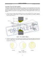
Page 10: ...idelines for the location of the detector if Forney s Burner Redline Review service is not utilized 1 The best results are obtained when the detector is aimed so that the detector s line of sight intersects the burner center at a slight angle e g 5 degrees and sees a maximum of the primary combustion zone as shown in Figure 3 Figure 3 Line of Sight Installation 2 The detector should have an unrest...

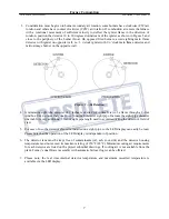
Page 11: ... inches is desired for optimal view of a flame through a 4 foot windbox Use no more than one foot of one inch diameter sight pipe Increase the sight pipe diameter one inch for every additional 2 feet of sight pipe length used to avoid restricting the detector s field of view 5 For ease of use the detector should be installed on a sight pipe so the LED display can easily be read Please note that th...

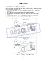
Page 12: ...gnition systems Because the UNIFLAME Series flame detectors require 24 Vdc power for operation connection of a 24 Vac 120 Vac or 220 Vac power source will damage the detector Therefore external 2 0 Amp fuses are recommended to protect the processor flame relay and the fault relay contacts See Figure 6 Figure 6 Cable Connection Notes 1 Flame relay contacts are shown in the de energized no flame con...

Page 13: ...d cracked or dirty oily ignition wires Ignition wire must be in good working condition 4 Electrically isolate the detector from the burner using the surface mounting flange provided 5 Attach drain wire of the detector cable to earth ground of power supply 6 For remote communications less than 200 feet connect drain wire of the communication cable to earth ground of power supply Figure 7 Connection...

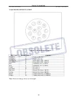
Page 14: ...dc White Blue B Power 24 Vdc White Black C Flame Relay N O contacts White Red D Flame Relay N O contacts Red E Fault Relay N C contacts Pink F Fault Relay N C contacts Violet G 4 20 mA Grey Red H 4 20 mA Blue Red J Remote File Select 1 RFS1 Yellow K Remote File Select 2 RFS2 Brown L Communications A COMM A Orange M Communications B COMM B Note Brown and orange wires are a twisted pair 10 ...

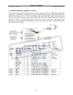
Page 15: ... remaining four 4 terminals are used to daisy chain the remote communication wires from one detector to another Figure 10 Wiring Harness Assembly Layout Cable Wire Color Terminal Function Termination Black Red 1 Power 24 Vdc White Blue 2 Power 24 Vdc Detector White Black 3 Flame Relay N O contacts Back to Cable White Red 4 Flame Relay N O contacts the Control Red 5 Fault Relay N C contacts Room Pi...

Page 16: ...nt system For wiring distances greater than 200 feet Figure 12 wire the twisted shielded pair of wires in a multi drop wiring configuration and then use a terminating resistor at the detector located farthest from the communication source The maximum distance for the communication wiring for all associated UNIFLAME Series detectors is 4 000 feet The maximum number of detectors connected to the com...

Page 17: ...iles when RFS1 or RFS2 wires are connected to 24 Vdc RFS1 Blue Wire Pin J RFS2 Yellow Wire Pin K File Selected Open Open A Closed Open B Open Closed C Closed Closed D The user may also select RFS as KEY which will allow manual file selection at the detector keypad or select COMM which will allow manual selection at a remote computer running the Forney SMARTDisplay Software Forney recommends the us...

Page 18: ...p Down keys Use UP and DOWN keys to scroll through the detector s menus When in the EDIT mode use the UP and DOWN keys to change the selected setpoint Select key When in the EDIT mode press the SELECT key to display the stored value of the setpoint Use the UP DOWN keys to change the value Press the SELECT key a second time although a setpoint has been changed to return to the menu without saving t...

Page 19: ... digit password must be entered prior to entering the EDIT or AUTOTUNE modes A summary of the text displayed in the STATUS LOOP is provided below and shown in Figure 15 TEXT DISPLAYED DESCRIPTION POSSIBLE VALUES FQ 0 Flame Quality detector output 0 100 FLAME ON Flame relay status ON OFF T 46C Present detector temperature 40 F to 185 F 40 C to 85 C File A Detector file in operation A B C D i0 u0 Si...

Page 20: ... mode File Selected The current running file is displayed Choices are A B C or D Signal Strength The Signal Strength number represents the intensity of the Bandpass as sensed by the IR and or UV sensor s The number is a function of the individual sensor s Gain and Bandpass settings Comm Address This number refers to the remote communications address of the flame detector The address can range from...

Page 21: ...o change the value from a 0 to a 5 5 With the appropriate fourth digit selected press PROGRAM to confirm the value 0205 If the password was not entered correctly the display will read Wrong Password Press SELECT to re enter the password If the password was entered correctly the display will read Valid Password Press SELECT to Change Password If you wish to change the password press the SELECT key ...

Page 22: ...on conditions The detector will then automatically select the optimum setpoints The automatic selections of optimum setpoints include the appropriate sensor gain bandpass frequency sensor range and flame relay ON and OFF thresholds The AUTOTUNE mode is entered from the STATUS LOOP by first entering a four digit password A summary of the text displayed in the EDIT mode is provided below and shown i...

Page 23: ...w O2 and press the PROGRAM key The detector will display Wait followed by a number that will count down from 128 to 0 in about 20 seconds This will temporarily store the spectrum of the monitored flame and adjacent flames The front end gain number used in the ON OFF calculation will be stored at this time Learn OFF Turn off the monitored flame leaving adjacent flames operating in a normally operat...

Page 24: ... KEY POSSIBLE VALUES UP DOWN KEYS File Select FILE A A B C D Temperature Scale Scale C C F Comm Address COMM 0 0 127 Remote File Select RFS KEY KEY LINE COMM File Copy A Language English English Sensors UV IR MultiSpectral Model Only UV IR IR Only UV Only IR Band i23 0 IR frequency Signal Strength 23 31 39 46 54 62 70 78 85 93 101 109 117 125 132 140 148 156 164 171 179 Hz IR Gain IG31 0 IR gain S...

Page 25: ...iles F1 F2 contain factory settings For file F1 the sensor gain is set at maximum 31 and the band target flame flicker frequency is set at 23 Hz At these settings the detector will respond to almost any flame but will not discriminate between target flame and other nearby flames For File F2 the sensor gain is set at minimum 1 and the band is set at 70 Hz At these settings the detector will not res...

Page 26: ...keys changes the gain displayed and immediately stores the value pressing the PROGRAM key is not required The user will immediately see the effect on the Signal Strength Each increment of the gain will increase the Signal Strength number for the IR sensor by 50 e g changing IR sensor gain from 26 to 27 would increase the IR Signal Strength from 600 to 900 Each decrement of gain will decrease the S...

Page 27: ...uld be set to Low If when Aiming the detector an UV number of less than 10 is observed then the UV Range should be set to High ON Threshold This refers to the pull in threshold of the internal flame relay in terms of Flame Quality The ON Threshold can be set from 5 to 100 The ON Threshold must be at least 5 units higher than the OFF Threshold When the Flame Quality is equal to or greater than the ...

Page 28: ... replace detector 4101 through 4501 A D Failure Remove source of electrical interference Verify regulated 24 Vdc on Pin A B Re power detector to see if fault clears If not replace detector 5001 through 5201 Detector Failure Remove source of electrical interference Verify regulated 24 Vdc on Pin A B Re power detector to see if fault clears If not replace detector 6001 Relay Failure Replace or send ...

Page 29: ... returned by stock number model number 2 Reason for return 3 Company name and address of customer 4 Customer s requested mode for return shipping 5 Customer s purchase order number for repairs if applicable 6 Customer s requested return date 7 Name and address to which Forney is to return ship and any special container marking information that may be required 8 Name of individual customer s repres...

Page 30: ...ts List Part Description Part Number Qty Flame Detector 40111x xx 10 of qty required for boiler Power Supply 79508 51 1 for every 5 12 Cond Pre fab Cable 405842 xx 1 for every 10 Wiring Harness 401110 xx 1 for every 10 When ordering spare parts furnish the following information to Attn Spare Parts Department Forney Corporation 3405 Wiley Post Road Carrollton Texas 75006 5185 Phone 972 458 6100 1 8...

Reviews: