Forney Corporation
UNIFLAME User’s Manual
Publication 372000-48 Rev H
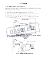
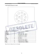
3.2 QUICK DISCONNECT LAYOUT
Figure 9 – Quick Disconnect Layout
Wire Color
Pin Designation
Function
Black/Red
A
Power (+) 24 Vdc
White/Blue
B
Power (-) 24 Vdc
White/Black
C
Flame Relay (N.O. contacts)
White/Red
D
Flame Relay (N.O. contacts)
Red
E
Fault Relay (N.C. contacts)
Pink
F
Fault Relay (N.C. contacts)
Violet
G
4-20 mA (+)
Grey/Red
H
4-20 mA (-)
Blue/Red
J
Remote File Select 1 (RFS1)
Yellow
K
Remote File Select 2 (RFS2)
Brown
L
Communications A (COMM A)
Orange
M
Communications B (COMM B)
Note:
Brown and orange wires are a twisted pair.
10


