P/N 1070341 • REV 2.0 • ISS 22FEB11
9 / 56
EN: Installation Sheet
Description
This manual provides information for the following four-door
access control data gathering panel (DGP): ATS1251,
ATS1252, ATS1253 and ATS1254. When referring to the four-
door DGP, this can be read as any variant of the ATS125x,
unless specifically stated otherwise.
Table 1: List of existing four-door DGP variants
Variant Auxiliary
power
Locks
power
Housing Dimensions
ATS1251 12
V 12
V
ATS1642 (big)
480x464x160 mm
ATS1252 12
V 24
V * ATS1642 (big)
480x464x160 mm
ATS1253 12
V 12
V
ATS1640 (small) 445x315x90 mm
ATS1254 12
V 24
V * ATS1640 (small) 445x315x90 mm
* In case of 24 VDC variant always use 2 batteries in series.
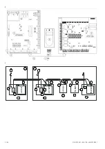
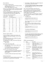
ATS125x four-door DGP overview
Figure 1 legend
Item Description
1.
DIP switches (see “DIP switch settings” on page 12).
2.
RAM or IUM (optional).
3. EPROM
(factory
fitted).
4.
KILL jumper - Factory default ATS125x when shorted.
5.
Battery fuse F1.
6.
Auxiliary power fuse F2.
7.
Databus 1 fuse F3.
8.
Databus 2 fuse F4.
9.
Lock power 1 fuse F5.
10.
Lock power 2 fuse F6.
11.
Siren / switch fuse F7
12. L1-L4
LED
13.
TERM 1. Use this link to terminate the system databus.
14.
TERM 2. Use this link to terminate the local databus,
connection 1 on terminal CON9.
15.
TERM 3. Use this link to terminate the local databus,
connection 2 on terminal CON10.
16.
CON14 Input expander connector
17.
CON15 Output expander connecter
18. Mains
terminal
Connections
Table 2: ATS125x connections
Terminal
block
Wire Description
CON1
,
Mains power connection
System earth (see details on page 11).
+,
−
2 x 12 V batteries, 7.2 Ah (24 V
version)*
1 x 12 V battery, 7.2 Ah (12 V version)
Terminal
block
Wire Description
CON2 +,
−
Aux.
power
+,
−
Aux.
power
S+,
S
−
**
External siren output
CON3 +,
−
Lock 1 power
+,
−
Lock 2 power
CON4
NO, COM, NC
Door 1 relay
NO, COM, NC
Door 2 relay
CON5
NO, COM, NC
Door 3 relay
NO, COM, NC
Door 4 relay
CON6
0V, D+, D
−
System databus and panel tamper
wiring (see “ATS system databus
connection” on page 11 for details).
T, C
Tamper switch
CON7
1, 2, 3, 4
Zone 1-4 inputs
C
Common
CON8
5, 6, 7, 8
Zone 5-8 inputs
C
Common
CON9
12V, 0V, D+, D
−
Local databus to connect RASs and
DGPs (see “ATS125x local databus
and earth connection” on page 11 for
details).
CON10
12V, 0V, D+, D
−
Local databus to connect RASs and
DGPs (see “ATS125x local databus
and earth connection” on page 11 for
details).
*
In case of 24 VDC variant always use two batteries in series.
**
External siren output is a supervised output. Typical EOL resistor
is 1 k
.
Mains power connection
Use the mains terminal to connect the mains-supply. A fixed
cable, or a flexible mains lead to an earthed mains outlet, can
be used. In case fixed wiring is used, insert a dedicated circuit
breaker in the power distribution network.
WARNING:
Electrocution hazard. To avoid personal injury or
death from electrocution, remove all sources of power and
allow stored energy to discharge before installing or removing
equipment.
Battery removal/disposal
This product contains one (or more) sealed, rechargeable, BS-
type lead-acid battery. It is a maintenance-free, leakproof,
long-life battery that should not be removed under normal
circumstances. Because removing the battery may affect the
product's configuration settings or trigger an alarm, only a
qualified installer should remove the battery.
To remove the battery, do the following:
1. Make sure that your product settings allow you to open its
cover without starting the tamper alarm.
2. Switch off the mains power, if necessary, and remove the
cover.


