background image

P/N 146552999-1 (ML) • REV D • ISS 23MAY12 


29 / 36 

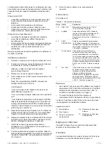
Lp. Opis 

SW1-5 

Zdalny 

w

ł

. SW1-5 

Zdalny 

wy

ł

.

Inne Tryb 

eko  W

łą

czony w trybie 

dziennym bez WT 

Wy

łą

czony 

 Pami

ęć

 alarmu  W

łą

czona w trybie 

dziennym bez WT 

Wy

łą

czona 

Patrz równie

ż

 „Po

łą

czenia” na stronie 27. 

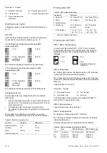
SW1-6: Diody LED 

W

ł

.: Diody LED w

łą

czone. Funkcje diod LED — patrz „Diody 

LED i wyj

ś

cia” ni

ż

ej. 

Wy

ł

.: Diody LED wy

łą

czone w ka

ż

dym stanie. 

Ksza

ł

towanie charakterystyki pokrycia 

czujki  

• Usu

ń

 przes

ł

ony w razie potrzeby (Rysunek 8, pozycja 1). 

Zmodyfikowane charaktetystyki s

ą

 pokazane na 

Rysunku 8, pozycje od 3 do 7. 

Uwaga: 

je

ż

eli obie przes

ł

ony pozostan

ą

 za

ł

o

ż

one, zasi

ę

czujki jest ograniczony do 6 m (domy

ś

lnie). 

• Mo

ż

liwa jest modyfikacja charakterystyki przez 

wy

ł

amywanie cz

ęś

ci przes

ł

ony (pokazane jako 

wyszarzone fragmenty  na Rysunku 8, pozycja 1). 
Odpowiadaj

ą

ce fragmenty kurtyn s

ą

 pokazane na 

Rysunku 8, pozycja 2. 

• Naklej 

wyklejki 

na 

lustra w celu zamaskowania cz

ęś

ci 

kurtyny. Zobacz szczegó

ł

y na Rysunku 7, pozycja 1. 

Przestroga: 

Usuwanie naklejonych elementów mo

ż

uszkodzi

ć

 powierzchni

ę

 lustra. 

• Je

ż

eli bezpo

ś

rednio pod czujk

ą

 znajduj

ą

 si

ę

 przeszkody, 

nale

ż

y za

ł

o

ż

y

ć

 odpowiedni

ą

 przes

ł

on

ę

 (jest za

ł

o

ż

ona 

domy

ś

lnie). Zobacz Rysunek 7, pozycja 2. 

Testowanie czujki 

Istniej

ą

 dwa sposoby w

łą

czenia trybu testu przej

ś

cia. 

Prze

łą

cznik SW1-6 ustawiony na Dioda LED w

ł

., a 

prze

łą

cznik SW1-5 na Zdalny wy

ł

W tym trybie sygnalizacja LED jest zawsze w

łą

czona (sta

ł

tryb testu przej

ś

cia). 

Prze

łą

cznik SW1-6 ustawiony na Dioda LED w

ł

., a 

prze

łą

cznik SW1-5 na Zdalny w

ł

Przy tym ustawieniu w

łą

czone jest wej

ś

cie testu przej

ś

cia 

(styk 7) i wej

ś

cie dzie

ń

/noc (styk 8). Umo

ż

liwia to 

u

ż

ytkownikowi zdalne w

łą

czenie sygnalizacji LED przez 

przestawienie czujki w tryb dzienny oraz aktywacj

ę

 testu 

przej

ś

cia. 

Tryb ekologiczny 

Gdy prze

łą

cznik SW1-5 jest ustawiony na Zdalny w

ł

., radar jest 

wy

łą

czony w trybie dziennym (bez WT) w celu ograniczenia 

poboru pr

ą

du. Czujka dzia

ł

a wówczas tylko w trybie PIR.  

Uwaga: 

Aby ten tryb dzia

ł

a

ł

, linia dzie

ń

/noc musi by

ć


pod

łą

czona do centrali. 

Pami

ęć

 alarmu 

Gdy prze

łą

cznik SW1-5 jest ustawiony na Zdalny w

ł

., alarmy, 

które wyst

ą

pi

ł

y w trybie nocnym, s

ą

 zapisywane w pami

ę

ci 

czujki. S

ą

 one sygnalizowane przez migaj

ą

c

ą

 na czerwono 

diod

ę

 LED po prze

łą

czeniu urz

ą

dzenia w tryb dzienny (test 

przej

ś

cia wy

łą

czony). Pami

ęć

 jest czyszczona po ponownym 

prze

łą

czeniu czujki w tryb nocny. 

Uwaga: 

Aby zapobiec pokazywaniu pami

ę

ci alarmu przez 

diody LED, nale

ż

y ustawi

ć

 prze

łą

cznik SW1-6 na Off (Wy

ł

.). 

Patrz „SW1-6: Diody LED” wy

ż

ej. 

Diody LED i wyj

ś

cia 

Aby w

łą

czy

ć

 funkcje diod LED, nale

ż

y ustawi

ć

 prze

łą

cznik 

SW1-6 na On (W

ł

.); w przeciwnym razie diody LED b

ę

d

ą


wy

łą

czone w ka

ż

dym stanie. Aby uzyska

ć

 wi

ę

cej szczegó

ł

ów, 

patrz „SW1-6: Diody LED” wy

ż

ej. 

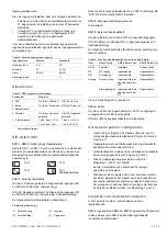
Tabela 5: Diody LED i wyj

ś

cia 

Status 

Czerwo

na 

diod

a LED 

Przeka

ź

nik 

alarmo

wy 

Przeka

ź

nik 

sygnalizacji


usterek 

Resetowanie 

Uruchomienie 


Zw. Zw. Automatycznie 

po 

60 s. 

Niskie napi

ę

cie 


Rozw. Rozw. Zastosuj 

prawid

ł

owe 

napi

ę

cie 

Alarm intruza PIR 


Zw. Zw.  

Alarm intruza 
mikrofalowy 


Zw. Zw.  

Podwójny alarm 
wykrywania ruchu 
intruza 


Rozw. Zw. 

Automatycznie 

po 

3 s. 

Zablokowany PIR 
(pami

ęć


Zw. Zw. Prze

łą

cz w tryb 

nocny 


Ś

wieci w sposób ci

ą

g

ł

y   

 Miga normalnie (1 Hz) 

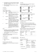
Dane techniczne 

Technologia czujki 

Dualna 

Zasi

ę

10, 12, 14, 16 m, wybierany za pomoc

ą


prze

łą

czników SW1-1 i SW1-2 

K

ą

t widzenia 

78 stopni 

Optyka PIR 

9 kurtyn lustrzanych o wysokiej 
g

ę

sto

ś

ci 

Cz

ę

stotliwo

ść

 mikrofalowa 

5,8 GHz 

Maks. moc wyj

ś

ciowa 

mikrofal przy 1 m 

0,003 

μ

W/cm² 

Funkcja pami

ę

ci Tak 

Zasilanie 

od 9 do 15 V

 (nominalnie 12 V) 

Odporno

ść

 na t

ę

tnienia 

2 V (przy 12 V

Czas uruchamiania czujki 

60 s 

Pobór pr

ą

du 

od 5 do 16 mA (nominalnie 8 mA) 

Wysoko

ść

 monta

ż

od 1,8 do 3,0 m 

Zakres pr

ę

dko

ś

ci celu 

od 0,2 do 3,0 m/s 

Charakterystyka przeka

ź

nika 

Alarm (NC) / Sabota

ż


80 mA 30 V

, Typ A  

Summary of Contents for Interlogix DDV1016

Page 1: ...01 1 Form 170 x 120 mm double sided printing stapled booklet 2 Fold twice to fit in box UTC Fire Security Manual DDV1016 White paper 75 gr m progresso overprint black 14 6552 999 1 1 A 16 12 11 B 20 01 12 C 6 04 12 D 23 05 12 ...

Page 2: ... A B C B C 2 1 2 3 3 4 3 16 m range 52 ft 6 in 0 m 2 m 6 ft 6 in 4 m 13 ft 1 in 6 m 19 ft 8 in 8 m 26 ft 2 in 2 m 6 ft 6 in 4 m 13 ft 1 in 6 m 19 ft 8 in 8 m 26 ft 2 in 10 m 32 ft 9 in 10 m 32 ft 9 in 12 m 39 ft 4 in 12 m 39 ft 4 in 3 67 12 ft m 16 52 ft 6 in 0 m 2 4 m 7 ft 10 in optimum Note for INCERT installations Outer curtain sets 1 and 9 have 12 m range Detector mounting height must be 2 to ...

Page 3: ...8 m range 1 2 5 5 curtains 16 m range 6 7 curtains 16 m range 7 9 curtains 16 m range 9 7 Walk test 3 8 Day night 4 47K 47K 12K 12 V SW1 3 On Polarity Active high 1 7 Walk test 3 8 Day night 4 47K 47K 12K 12 V SW1 3 Off Polarity Active low 2 Walk test On Walk test Off Night armed Day disarmed Pin 7 to GND Pin 7 to 12 V or floating Pin 8 to GND Pin 8 to 12 V or floating Walk test On Walk test Off N...

Page 4: ...a mounting bracket Use the following guidelines to determine the best location to install the detector Mount the detector so the expected movement of an intruder is across the detection pattern see Figure 3 Mount the detector at a stable surface at a height between 1 8 m and 3 0 m 5 9 and 9 8 ft from the floor Note For INCERT installations mounting height must be 2 0 to 3 0 m 6 6 to 9 8 ft Do not ...

Page 5: ...s use the SB01 swivel mount bracket SB01 mounting position is shown as item 1 in Figure 4 9 Close the cover insert the cover screw and place the custom insert Connections See Figure 12 Table 1 Detector Connections Terminal Label Explanation 1 2 GND 12V Power supply connection 9 to 15 V 12 V nominal 3 4 ALARM Alarm relay output 33 Ω Use jumper JA to set the onboard EOL resistor in series with the r...

Page 6: ...d day night inputs Off Remote off Disables WT and day night inputs factory default The following functionality depends on the Remote setting Table 4 Functions dependent on the Remote setting Item Description SW1 5 Remote on SW1 5 Remote off SW1 3 Polarity Selectable Positive only WT WT input Enabled Disabled D N D N input Enabled Disabled Other Green Mode Enabled in day mode with no WT Disabled Al...

Page 7: ...range 0 2 to 3 0 m s 8 in s to 10 ft s Alarm NC Tamper relay characteristic 80 mA 30 V Form A Alarm time 3 s Operating temperature 10 to 55 C 14 to 130 F Relative humidity 95 max noncondensing Weight 120 g Dimensions H x W x D 126 63 50 mm IP IK rating IP30 IK04 Pry off tamper Optional ST400 Regulatory information Manufacturer UTC Fire Security Americas Corporation Inc 1275 Red Fox Rd Arden Hills ...

Page 8: ...8 Til loftmontering anvendes SB01 svingmonteringskonsol SB01 monteringspositionen vises som pkt 1 i figur 4 9 Luk detektoren indsæt dækskrue og indsæt dækpladen Tilslutninger Se figur 12 Tabel 6 Detektortilslutninger Terminal Etiket Forklaring 1 2 GND 12V Strømforsyningstilslutning 9 til 15 V 12 V nominel Terminal Etiket Forklaring 3 4 ALARM Alarmrelæudgang 33 Ω Brug jumper JA til at sætte den ind...

Page 9: ... til Aktiverer WT og dag nat OFF Ekstern fra Deaktiverer WT og dag nat indgang fabriksindstilling Følgende funktion afhænger af ekstern indstilling Tabel 9 Funktion afhænger af ekstern indstilling Punkt Beskrivelse SW1 5 Ekstern til SW1 5 Ekstern fra SW1 3 Polaritet Valgbar Kun positiv WT WT indgang Tilkoblet Frakoblet D N D N indgang Tilkoblet Frakoblet Andet Grøn tilstand Aktiveret i dagtilstand...

Page 10: ...kevidde 10 12 14 16 m vælges via SW1 1 og SW1 2 Visningsvinkel 78 grader PIR optik 9 spejlgardiner med høj densitet Mikrobølgefrekvens 5 8 GHz Maks mikrobølge ved 1 m 0 003 μW cm Hukommelsesfunktion Ja Indgangseffekt 9 til 15 VDC 12 V nominel Peak to peak ripple immunitet 2 V ved 12 VDC Detektoropstartstid 60 sek Strømforbrug 5 til 16 mA 8 mA nom Monteringshøjde 1 8 til 3 0 m Indstilling af detekt...

Page 11: ... 6 6 bis 9 8 ft betragen Siehe Abb 4 Verwenden Sie für eine flache Montage mindestens zwei Schrauben DIN 7998 an den Positionen A Verwenden Sie für die Eckmontage die Schrauben in Position B oder C Um den Abreißkontakt für die Gehäuseüberwachung ST400 zu installieren verwenden Sie Montageposition A oder B Die Montageposition für ST400 wird in Abbildung 4 Element 3 dargestellt Öffnen Sie die Öffnun...

Page 12: ...degruppenstatus Wert Werkseinstellung Sabotage kurz 0 Ω 0 Ω Normal Rt 4 7 kΩ Alarm Rt Ra 9 4 kΩ Meldegruppenstatus Wert Werkseinstellung Sabotage offen DIP Schalter Tabelle 3 SW1 allgemeine Einstellungen Schalter Werte 6 LED Ein LED ein Aus LED aus 5 Remote Ein Remote ein Aus Remote aus 4 Reserviert 3 Polarität Ein Positive Polarität Aus Negative Polarität 1 2 Radar reichweite 1 Ein 2 Ein 16 m 1 A...

Page 13: ...haltet SW1 5 wird auf Remote ein geschaltet Diese Einstellung aktiviert den Gehtest Eingang Klemme 6 und den Scharf Unscharf Eingang Klemme 8 Auf diese Weise kann die LED Anzeige über einen Gehtestausgang der Zentrale im unscharfen Zustand aktiviert werden Grüner Modus Wenn SW1 5 auf Remote ein geschaltet wird ist der Radar im Unscharf Modus ohne WT deaktiviert um den Stromverbrauch zu senken Der ...

Page 14: ...e el detector sobre una superficie estable a una distancia del suelo de entre 1 8 m y 3 0 m No instale el detector a una distancia inferior a 0 5 m de objetos metálicos o 1 5 m de luces fluorescentes No coloque objetos delante del detector que puedan impedir una línea de visión clara Cuando coloque los detectores uno enfrente del otro colóquelos a una distancia de al menos 6 m entre sí y utilice u...

Page 15: ...ado el modo remoto Consulte SW1 5 Funcionalidad remota en la página 15 El LED solo está habilitado cuando SW1 6 tiene activado el LED La figura 10 explica cómo se crea una zona única con una configuración de resistencia múltiple Leyenda de la Figura 10 1 Relé de alarma 2 Zona de alarma 3 Salida del interruptor del tamper Ra Resistencia EOL de la alarma Rt Resistencia EOL del tamper Configuración d...

Page 16: ...ta Si ambas mascaras estan instalados el rango del detector se limita a 6m defecto Para modificar el patron se deben romper las mascaras mostradas en gris en la Figura 8 parte 1 Las correspondientes partes de cortinas se muestran en la Figura 8 parte 2 Si fuera necesario colocar las apropiadas etiquetas en los espejos Para mas detalles Figura 7 parte 1 Precaución Al retirar las etiquetas una vez c...

Page 17: ...Fox Rd Arden Hills MN 55112 6943 EE UU Representante de fabricación autorizado en la UE UTC Fire Security B V Kelvinstraat 7 6003 DH Weert Países Bajos Certificación 2002 96 EC directiva WEEE Los productos marcados con este símbolo no se pueden desechar como residuos urbanos no clasificados en la Unión Europea Para que se pueda realizar un reciclaje adecuado devuelva este producto a su representan...

Page 18: ...et ajouter les autocollants si nécessaire Voir Configuration de la couverture en page 19 pour plus détails 8 Pour les applications de montage au plafond utilisez la patte de fixation à pivot SB01 La position de montage de la patte de fixation SB01 est représentée par l élément 1 de la Figure 4 9 Fermez le cache insérez la vis puis replacez le couvercle Connexions Voir la Figure 12 Tableau 1 Connex...

Page 19: ...1 2 pour définir la portée du radar de sorte qu elle s adapte précisément à l application Ce radar inclut une fonction de crénelage spatial range gating ce qui signifie que la portée de détection est extrêmement précise ON 1 2 10 m ON 1 2 14 m ON 1 2 12 m ON 1 2 16 m Configuration d usine par défaut SW1 3 Polarité Position ON Polarité positive Configure les entrées WT test de marche et D N mode jo...

Page 20: ...onne alors en mode IRP seulement Remarque Pour que ce mode fonctionne la ligne Jour Nuit doit être connectée à la centrale Mémoire d alarme Lorsque le contrôle à distance du commutateur SW1 5 est activé les alarmes déclenchées en mode Nuit sont stockées dans la mémoire du détecteur Elles sont indiquées par un voyant rouge lumineux lorsque l unité passe en mode Jour test de marche désactivé La mémo...

Page 21: ... rilevatore è molto resistente ai rischi di falsi allarmi Tuttavia è opportuno evitare possibili fattori di instabilità quali Rischi PIR Esposizione del rilevatore alla luce solare diretta Fonti di calore nel campo di rilevazione del rilevatore Forti correnti d aria in prossimità del rilevatore Animali all interno del campo di rilevazione Oscuramento del campo di rilevazione del rilevatore con ogg...

Page 22: ...omissione Ra Resistenza allarme di fine linea EOL Rt Resistenza antimanomissione di fine linea EOL Impostazione del rilevatore Per le posizioni dei ponticelli e del DIP switch vedere la figura 13 Ponticelli I ponticelli consentono di definire la modalità e il valore di fine linea EOL sulla scheda Il circuito è visibile nella figura 10 JA Impostazione resistenza allarme Ra di fine linea EOL integra...

Page 23: ... 8 oggetto 1 Le porzioni di tende corrispondenti sono illustrate nella Figura 8 oggetto2 Mettere gli appropriati adesivi sullo specchio se necessario Vedere Figura 7 oggetto 1 per dettagli Attenzione La rimozione degli adesivi può danneggiare la superficie dello specchio Quando ci sono oggetti vicino direttamente sotto il sensore mettere la maschera all interno della finestra impostazioni di fabbr...

Page 24: ...iti come normali rifiuti Al momento dell acquisto di un apparecchiatura nuova analoga restituire il prodotto al fornitore locale o smaltirlo consegnandolo presso gli appositi punti di raccolta Per ulteriori informazioni consultare www recyclethis info Informazioni di contatto www utcfireandsecurity com o www interlogix com Per l assistenza clienti consultare www interlogix com customer support NL ...

Page 25: ...ant plaats de schroef in de behuizing en plaats het afdekplaatje Aansluitingen Zie afbeelding 12 Tabel 1 Detectoraansluitingen Aansluiting Label Verklaring 1 2 GND 12V Voedingsaansluiting 9 t m 15 V 12 V nominaal 3 4 ALARM Alarmrelaisuitgang 33 Ω Gebruik jumper JA om de ingebouwde EOL weerstand in serie te plaatsen met het relais Zie Jumpers hieronder 5 6 TAMPER Sabotagerelaisuitgang 0 Ω Gebruik j...

Page 26: ...SW1 5 instelling Zie SW1 5 Externe functionaliteit hieronder SW1 4 Niet gebruikt Gereserveerd Niet wijzigen SW1 5 Externe functionaliteit On Aan Extern aan Activeert WT en dag nachtingangen Off Uit Extern uit Schakelt WT en dag nachtingangen uit fabrieksinstelling De volgende functionaliteit is afhankelijk van de instelling voor Remote Extern Tabel 4 Functies zijn afhankelijk van de instelling Ext...

Page 27: ...eheugen G G Overschakelen naar de nachtmodus G Gesloten O Open Continu AAN Normaal knipperend 1 Hz Specificaties Detectortechnologie Dual Bereik 10 12 14 16 m instelbaar via SW1 1 en SW1 2 Kijkveld 78 graden PIR optiek 9 spiegelgordijnen met hoge dichtheid Radarfrequentie 5 8 GHz Max microgolfuitgang op 1 m 0 003 μW cm Geheugenfunctie Ja Aansluitspanning 9 t m 15 V 12 V nominaal Immuniteit rimpels...

Page 28: ...rub DIN 7998 umieszczając je w pozycji A W przypadku montażu narożnego użyj śrub w pozycji B lub C Aby zainstalować zabezpieczenie przed oderwaniem ST400 użyj pozycji montażowej A lub B Pozycja montażowa elementu ST400 jest pokazana jako poz 3 na rys 4 Otwórz wylot w płycie tylnej rys 5 poz 2 5 Podłącz okablowanie czujki patrz rys 4 i 12 Użyj wlotów kablowych w płycie tylnej rys 5 poz 1 i kanału k...

Page 29: ...stawienia ogólne Przełącznik Wartości 6 Dioda LED Wł Dioda LED wł Wył Dioda LED wył 5 Zdalny Wł Zdalny wł Wył Zdalny wył 4 Zarezerwowany 3 Polaryzacja Wł Polaryzacja dodatnia Wył Polaryzacja ujemna 1 2 Zasięg radaru 1 wł 2 wł 16 m 1 wył 2 wł 14 m 1 wł 2 wył 12 m 1 wył 2 wył 10 m Domyślne ustawienie fabryczne Przełącznik DIP SW1 SW1 1 SW1 2 Zasięg radaru Za pomocą przełączników SW1 1 i SW1 2 można ...

Page 30: ...cznik SW1 5 jest ustawiony na Zdalny wł radar jest wyłączony w trybie dziennym bez WT w celu ograniczenia poboru prądu Czujka działa wówczas tylko w trybie PIR Uwaga Aby ten tryb działał linia dzień noc musi być podłączona do centrali Pamięć alarmu Gdy przełącznik SW1 5 jest ustawiony na Zdalny wł alarmy które wystąpiły w trybie nocnym są zapisywane w pamięci czujki Są one sygnalizowane przez miga...

Page 31: ...s dos outros e utilize a definição de curto alcance para evitar interferências ao montar os detectores virados um para o outro A tecnologia de duplo processamento deste detector é muito resistente ao perigo de falsos alarmes No entanto evite potenciais causas de instabilidade tais como Perigos PIR Luz solar directa no detector Fontes de calor dentro do campo de visão do detector Correntes de ar fo...

Page 32: ... explica como criar uma zona única com uma configuração de resistência múltipla Legenda da figura 10 1 Relé de alarme 2 Zona de alarme 3 Saída do interruptor de tamper Ra Resistência EOL de alarme Rt Resistência EOL de tamper Configuração do detector Consulte a Figura 13 para ver as localizações dos jumpers e DIP switches Jumpers Os jumpers definem o modo e o valor do EOL integrado O circuito é mo...

Page 33: ... alcance do detetor é limitado a 6m de fábrica Modique o padrão através partes das máscaras indicado na Figura 8 item 1 a cinzento A correspondência com os fragmentos de cortinas é indicado na Figura 8 item 2 Coloque os autocolantes apropriados se necessário Para mais informação ver figura 7 item 1 Atenção A remoção dos autocolante pode danificar a superfície do espelho Quando existem por baixo do...

Page 34: ...éctricos e Electrónicos Os produtos marcados com este símbolo não podem ser eliminados como lixo municipal não separado na União Europeia Para uma reciclagem adequada devolva este equipamento ao fornecedor local aquando da compra de um novo equipamento equivalente ou coloque o num ponto de recolha designado para o efeito Para mais informações consulte www recyclethis info Informação de contacto ww...

Page 35: ...ående larmrelä 33 Ω Använd bygel JA för att ställa in den inbyggda EOL motståndet i serie med reläet Se Byglar nedan 5 6 SABOTAGE Utgående sabotagebrytare 0 Ω Använd bygel JT för att ställa in den inbyggda EOL motståndet i serie med kontakten Se Byglar nedan 7 Gångtest Denna ingång aktiverar och inaktiverar lysdioden gång test Till Från Gångtestläge kan bara aktiveras när detektorn är i dagläge pi...

Page 36: ...D N D N ingång Inkopplad Frånkopplad Övrigt Grönt läge Aktiverad i dagläge utan WT Frånkopplad Larmminne Aktiverad i dagläge utan WT Frånkopplad Se även Anslutningar på sidan 34 SW1 6 LED lampor På LED lamporna är aktiverade Se LED lampor och utgångar på sidan 36 för LED funktionalitet Av LED lamporna är inaktiva för alla lägen Inställning av täckningsområdet Ta bort maskskydden Bild 8 punkt 1 om ...

Page 37: ...Max Mikrovågeffekt på 1 meter 0 003 μW cm Minnesfunktion Ja Ingångsspänning 9 15 V 12 V nominal Vpp rippelresistens 2 V vid 12 V Uppstartningstid 60 sekunder Aktuell strömförbrukning 5 16 mA 8 mA nom Monteringshöjd 1 8 3 0 m Objektets rörelsehastighet 0 2 3 0 m s Larm NC sabotagerelä egenskaper 80 mA 30 V Form A Larmtid 3 sekunder Drifttemperatur 10 till 55 C Relativ fuktighet 95 max ej kondensera...

Reviews: