Chapter 8
Controller firmware tools
119
Administration menu
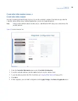
The Administration menu contains the following options:
•
Apply Changes:
applies new changes. See below.
•
Restart Application:
makes changes permanent. See below.
•
Restart Controller:
reboots the controller. See below.
•
Restore Factory Defaults:
restores factory defaults. See page 119.
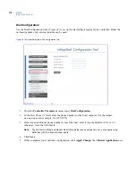
Apply Changes
Click this menu item to apply any new changes made to the controller’s configuration. The changes will
become active after you select
Restart Application,
as described next.
Restart Application
Click this menu item to make the changes to the controller permanent. The Integrated Configuration Tool will
shut down and then read the updated config file when it starts up again, making all applied changes active.
Restart Controller
Click this menu item to shut down and restart the controller. This option should only be used to reboot the
computer after you:
•
Enable/disable the Integrated Configuration Tool, as described in
Other Parameters
on page 117, or
•
Flash the controller, as described in
Flash controller menu/Flash controller
on page 121.
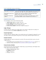
Restore Factory Defaults
Use this option to restore all of the controller’s default settings, except the IP address. The PXNplus board is
shipped with the following default settings:
•
Primary Connection Type:
Ethernet
•
IP Address:
192.168.6.6
•
Mask:
255.255.255.0
•
Gateway:
192.168.6.1
Enable/Disable Lock on Duress
Control if a door will lock and signal a threatening situation when a duress PIN code
is entered at a reader. (
Note:
This option is available for Picture Perfect only.)
Enable/Disable Passive Time &
Attendance
Determine if a door will unlock regardless of a credential's IN/OUT status.
(
Note:
This option is available for Picture Perfect only.)
Enable/Disable taped badge
suspend
C
ontrol how credentials are handled when an invalid PIN is entered in multiple
access attempts. (
Note:
This option is available for Picture Perfect only.)
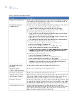
Table 35. Parameters/Other Parameters options (continued)
Parameter
Description
Summary of Contents for M3000
Page 1: ...M3000 Installation Manual P N 460630001H 15JUNE11 ...
Page 10: ...M3000 Installation Manual x ...
Page 39: ...Chapter 3 Power Communications board 29 Figure 11 Wiring modem to M3000 M 5 or serial printer ...
Page 47: ...Chapter 4 PXNplus CPU board 37 Board layout Figure 16 PXNplus CPU board layout ...
Page 58: ...M3000 Installation Manual 48 Board layout Figure 17 2RP reader board layout ...
Page 68: ...M3000 Installation Manual 58 Figure 24 Wiring 2RP door strike external relay ...
Page 72: ...M3000 Installation Manual 62 Board layout Figure 27 2SRP supervised reader board layout ...
Page 82: ...M3000 Installation Manual 72 Figure 19 Wiring 2SRP door alarm contact and exit request ...
Page 84: ...M3000 Installation Manual 74 Figure 21 Wiring 2SRP door strike external relay ...
Page 89: ...Chapter 5 Reader processing boards 79 Board layout Figure 24 8RP reader board layout ...
Page 92: ...M3000 Installation Manual 82 Figure 26 Wiring 8RP to F 2F or Supervised F 2F Readers ...
Page 94: ...M3000 Installation Manual 84 ...
Page 97: ...Chapter 6 Optional DI and DO boards 87 Figure 31 20DI board layout ...
Page 99: ...Chapter 6 Optional DI and DO boards 89 Figure 32 Wiring DI point ...
Page 101: ...Chapter 6 Optional DI and DO boards 91 Figure 33 16DO board layout ...
Page 102: ...M3000 Installation Manual 92 Figure 34 16DOR board layout ...
Page 104: ...M3000 Installation Manual 94 Figure 36 Wiring output device to 16DOR board ...
Page 152: ...M3000 Installation Manual 142 ...
Page 156: ...M5 controller Installation Manual 146 Figure 76 Installing ferrite ...
Page 160: ...M5 controller Installation Manual 150 ...
Page 172: ...M3000 Installation Manual 162 ...

