M3000
Installation Manual
130
The eFlash configuration file
The eFlash configuration file is an optional file located at
\root\cas\log\.eflashrc
. A Picture Perfect
operator can use this file to define flashing requirements for the entire system once, and then use part or all of
the definition to flash or reflash controllers as needed. This file can be used for scheduling unattended flashing.
This file can contain a combination of command line arguments, processing rules, and comments.
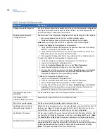
Table 37. eFlash configuration file
Arguments
All of the following command line options can be included, either one per line or you may
concatenate many options per line.controller
-p<directory>
Specifies the source directory to search for
flash files. This replaces the default directory
of /cas/flash/ eflash.
-f<filename>
Specifies a flash file to use instead of the
default flash used for direct connect type
controllers (PX).
-n<filename>
Specifies a flash file to use instead of the
default flash used for network type controllers
(PXN).
-m<micro id>
Specifies the controller or controllers to be
flashed.
-m a
Specifies that all active controllers in the
Picture Perfect database be flashed.
-l<micro id>
Specifies a controller in a line of controllers,
where the entire line is to be flashed.
Note:
If options are repeated, only the last value read from the file is used. The
exceptions are the -m and -l options, which use all specified controllers.
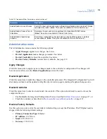
Processing Rules
Parameters that control the flashing of the controllers during the current execution of
eFlash may be included. The following two parameters may be included:
flashwait=value(in seconds)
Sets the time that eFlash waits for the
controller to actually flash the EPROM. The
flash of a controller is considered a failure if
the flash times out. The default is 90
seconds.
maxflash=value(in seconds)
Sets the maximum number of controllers that
can be flashed simultaneously. The actual
number of controllers that is being currently
flashed will always be less than this value
due to restrictions on flashing multiple
controllers in the same line. The default is 5.
Note
: Setting this number to a higher value
can impact the response time of the
system. You should keep this number
low for best performance.
Comments
The eFlash configuration file may contain comments. A comment is a line that begins
with the pound sign (#). The pound sign and all characters up through the next carriage
return are ignored.
Summary of Contents for M3000
Page 1: ...M3000 Installation Manual P N 460630001H 15JUNE11 ...
Page 10: ...M3000 Installation Manual x ...
Page 39: ...Chapter 3 Power Communications board 29 Figure 11 Wiring modem to M3000 M 5 or serial printer ...
Page 47: ...Chapter 4 PXNplus CPU board 37 Board layout Figure 16 PXNplus CPU board layout ...
Page 58: ...M3000 Installation Manual 48 Board layout Figure 17 2RP reader board layout ...
Page 68: ...M3000 Installation Manual 58 Figure 24 Wiring 2RP door strike external relay ...
Page 72: ...M3000 Installation Manual 62 Board layout Figure 27 2SRP supervised reader board layout ...
Page 82: ...M3000 Installation Manual 72 Figure 19 Wiring 2SRP door alarm contact and exit request ...
Page 84: ...M3000 Installation Manual 74 Figure 21 Wiring 2SRP door strike external relay ...
Page 89: ...Chapter 5 Reader processing boards 79 Board layout Figure 24 8RP reader board layout ...
Page 92: ...M3000 Installation Manual 82 Figure 26 Wiring 8RP to F 2F or Supervised F 2F Readers ...
Page 94: ...M3000 Installation Manual 84 ...
Page 97: ...Chapter 6 Optional DI and DO boards 87 Figure 31 20DI board layout ...
Page 99: ...Chapter 6 Optional DI and DO boards 89 Figure 32 Wiring DI point ...
Page 101: ...Chapter 6 Optional DI and DO boards 91 Figure 33 16DO board layout ...
Page 102: ...M3000 Installation Manual 92 Figure 34 16DOR board layout ...
Page 104: ...M3000 Installation Manual 94 Figure 36 Wiring output device to 16DOR board ...
Page 152: ...M3000 Installation Manual 142 ...
Page 156: ...M5 controller Installation Manual 146 Figure 76 Installing ferrite ...
Page 160: ...M5 controller Installation Manual 150 ...
Page 172: ...M3000 Installation Manual 162 ...


