M3000
Installation Manual
40
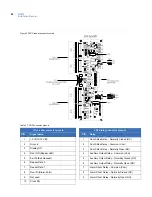
LED indicators
LEDs on the PXNplus CPU board
The LED state depends on which state the controller is in. There are two main modes with several substates:
•
Maintenance mode:
indicates the state of the controller before any application is running. There are
two maintenance mode states:
•
Boot mode
- indicates the bootloader is running and loading, verifying and invoking the run-time
images. This is a status LED only.
•
OS (operating system) maintenance mode
- the controller enters this mode after boot mode
when it first comes up and when it is never configured before. Holding JP3 will force the
controller into this mode.
•
Normal operation mode:
indicates the state of the controller after the application is downloaded. Use
the Integrated Configuration Tool to select the application. During this mode, the following additional
states can occur:
•
Controller offline:
indicates the controller has lost communication with the host.
•
Address received:
indicates the controller received a message from the host.
•
Badge read OK:
indicates the controller decoded a badge read and determined that it was a valid
badge.
•
Waiting for database
1
:
the controller is waiting to receive database from host.
•
Restore defaults requested:
indicates Jumper J3 was shorted. This requests that the defaults be
restored. The defaults are listed on page 119.
•
Shutdown requested:
indicates Jumper J6 was shorted. This requests that the application shut
down so that a hard reset can be done.
•
eFlash image save:
indicates that the newly loaded image from the eFlash transfer is being saved
into the FLASH. This is an activity indicator only.
•
Persistence:
indicates that the controller is operating without a host. In this mode, the controller is
operating standalone until communication is re-established with the host.
Items to note:
•
Upon restoration of communications with the host, the host automatically sets badge status for
Anti-passback and Time and Attendance to neutral for all badges on the controller.
•
Unknown badges cannot be learned because the controller is not online with the host. The
Unknown badge transactions are mislabeled in the history upload as transaction type
Learn
Timeout
instead of
Unknown Badge
.
•
Flash write:
indicates that the controller is storing database records into the Flash file system.
This is an activity indicator only.
•
Watchdog failure mode:
An internal thread failed. Details about the failure were logged
according to the log settings. The micro performs a complete reboot after this failure.
Summary of Contents for M3000
Page 1: ...M3000 Installation Manual P N 460630001H 15JUNE11 ...
Page 10: ...M3000 Installation Manual x ...
Page 39: ...Chapter 3 Power Communications board 29 Figure 11 Wiring modem to M3000 M 5 or serial printer ...
Page 47: ...Chapter 4 PXNplus CPU board 37 Board layout Figure 16 PXNplus CPU board layout ...
Page 58: ...M3000 Installation Manual 48 Board layout Figure 17 2RP reader board layout ...
Page 68: ...M3000 Installation Manual 58 Figure 24 Wiring 2RP door strike external relay ...
Page 72: ...M3000 Installation Manual 62 Board layout Figure 27 2SRP supervised reader board layout ...
Page 82: ...M3000 Installation Manual 72 Figure 19 Wiring 2SRP door alarm contact and exit request ...
Page 84: ...M3000 Installation Manual 74 Figure 21 Wiring 2SRP door strike external relay ...
Page 89: ...Chapter 5 Reader processing boards 79 Board layout Figure 24 8RP reader board layout ...
Page 92: ...M3000 Installation Manual 82 Figure 26 Wiring 8RP to F 2F or Supervised F 2F Readers ...
Page 94: ...M3000 Installation Manual 84 ...
Page 97: ...Chapter 6 Optional DI and DO boards 87 Figure 31 20DI board layout ...
Page 99: ...Chapter 6 Optional DI and DO boards 89 Figure 32 Wiring DI point ...
Page 101: ...Chapter 6 Optional DI and DO boards 91 Figure 33 16DO board layout ...
Page 102: ...M3000 Installation Manual 92 Figure 34 16DOR board layout ...
Page 104: ...M3000 Installation Manual 94 Figure 36 Wiring output device to 16DOR board ...
Page 152: ...M3000 Installation Manual 142 ...
Page 156: ...M5 controller Installation Manual 146 Figure 76 Installing ferrite ...
Page 160: ...M5 controller Installation Manual 150 ...
Page 172: ...M3000 Installation Manual 162 ...


