Chapter 5
Reader processing boards
57
Wiring door strikes
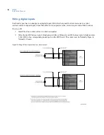
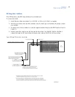
The 2RP provides a door DO relay dedicated to each reader port.
To wire a door strike:
1. Install the door strike (maximum 2 A @ 30 VDC or 0.50 A @ 120 VAC) as required.
2. Wire the door strike to the door DO (internal) relay. Normally open or Normally Closed dry contacts
are available.
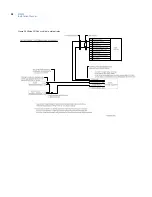
3. If required, wire the door strike to a customer supplied external relay and the 2RP board as shown in
Figure 22.
4. Install a protection diode across the relay and the door strike. Use 1N4002, 1N4003, 1N4004 or
equivalent diodes for DC door strikes and metal oxide varistors (MOV) for AC door strikes.
Figure 23.Wiring 2RP door strike - internal relay
Summary of Contents for M3000
Page 1: ...M3000 Installation Manual P N 460630001H 15JUNE11 ...
Page 10: ...M3000 Installation Manual x ...
Page 39: ...Chapter 3 Power Communications board 29 Figure 11 Wiring modem to M3000 M 5 or serial printer ...
Page 47: ...Chapter 4 PXNplus CPU board 37 Board layout Figure 16 PXNplus CPU board layout ...
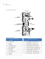
Page 58: ...M3000 Installation Manual 48 Board layout Figure 17 2RP reader board layout ...
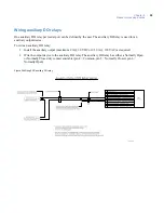
Page 68: ...M3000 Installation Manual 58 Figure 24 Wiring 2RP door strike external relay ...
Page 72: ...M3000 Installation Manual 62 Board layout Figure 27 2SRP supervised reader board layout ...
Page 82: ...M3000 Installation Manual 72 Figure 19 Wiring 2SRP door alarm contact and exit request ...
Page 84: ...M3000 Installation Manual 74 Figure 21 Wiring 2SRP door strike external relay ...
Page 89: ...Chapter 5 Reader processing boards 79 Board layout Figure 24 8RP reader board layout ...
Page 92: ...M3000 Installation Manual 82 Figure 26 Wiring 8RP to F 2F or Supervised F 2F Readers ...
Page 94: ...M3000 Installation Manual 84 ...
Page 97: ...Chapter 6 Optional DI and DO boards 87 Figure 31 20DI board layout ...
Page 99: ...Chapter 6 Optional DI and DO boards 89 Figure 32 Wiring DI point ...
Page 101: ...Chapter 6 Optional DI and DO boards 91 Figure 33 16DO board layout ...
Page 102: ...M3000 Installation Manual 92 Figure 34 16DOR board layout ...
Page 104: ...M3000 Installation Manual 94 Figure 36 Wiring output device to 16DOR board ...
Page 152: ...M3000 Installation Manual 142 ...
Page 156: ...M5 controller Installation Manual 146 Figure 76 Installing ferrite ...
Page 160: ...M5 controller Installation Manual 150 ...
Page 172: ...M3000 Installation Manual 162 ...


