


Imprimé au Canada
Conservez ce manuel pour références ultérieures.
Attention : Ne pas altérer
votre unité ou ses contrôles.
Appeler un technicien
qualifié.
Fabriqué par :
Division ICP
UTC Canada Corporation
2003/10/06
X40015 Rév. L
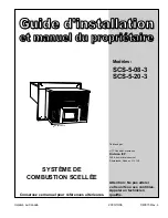
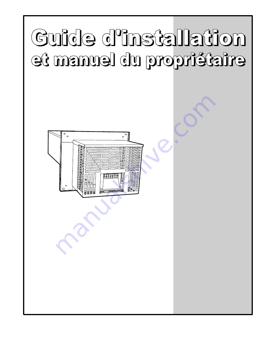
SYSTÈME DE
COMBUSTION SCELLÉE
Modèles:
SCS-5-08-3
SCS-5-20-3
DNS-0474 Rév A
3400, boulevard Industriel
Sherbrooke, Québec J1L 1V8
Summary of Contents for SCS-5-08-3
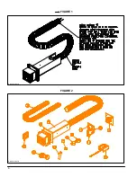
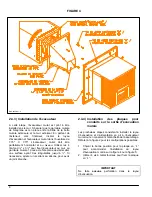
Page 5: ...6 FIGURE 1 FIGURE 2 DNS 0701 Rév B DNS 0501 Rév D ...
Page 6: ...7 VUE DE CÔTÉ FIGURE 3 DNS 0866 Rév A VUE ARRIÈRE ...
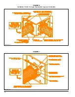
Page 12: ...13 FIGURE 11 POSITIONNEMENT DES TUBES CHAUDIÈRE AVEC SERPENTIN À GAUCHE DNS 0689 Rév C ...
Page 13: ...14 FIGURE 12 POSITIONNEMENT DES TUBES CHAUDIÈRE AVEC SERPENTIN À DROITE DNS 0690 Rév C ...
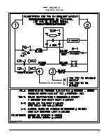
Page 16: ...17 FIGURE 13 Diagramme électrique DNS 0463 Rév C ...
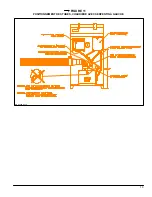
Page 17: ...18 FIGURE 14 Vérification de la pression totale de fonctionnement DNS 0499 Rév C ...
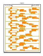
Page 20: ...21 LISTE DE PIÈCES Modèle SCS 5 DNS 0475 Rév I ...
Page 26: ...6 FIGURE 1 FIGURE 2 DNS 0701 Rev B DNS 0501 Rev D ...
Page 27: ...7 FIGURE 3 SIDE VIEW REAR VIEW DNS 0866 Rev A ...
Page 30: ...10 FIGURE 6 5 inches diameter Vent Pipe End Connection FIGURE 7 DNS 0481 Rev B DNS 0867 Rev A ...
Page 33: ...13 FIGURE 11 TUBES POSITION BOILER WITH TANKLESS COIL AT LEFT DNS 0689 Rev C ...
Page 34: ...14 FIGURE 12 TUBES POSITION BOILER WITH TANKLESS COIL AT RIGHT DNS 0690 Rev C ...
Page 37: ...17 FIGURE 13 Electric wiring diagram DNS 0643 Rev C ...
Page 38: ...18 FIGURE 14 Verification of the total operating pressure DNS 0499 Rév C ...


