10
Here are the icons
of the keys present in
the main mask
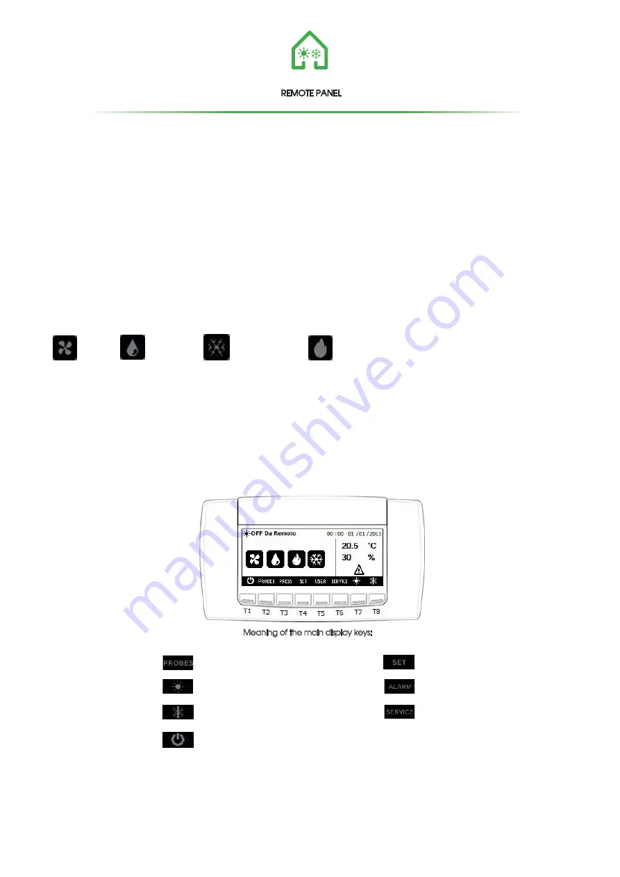
Meaning of the main display keys:
It allows the display of the value of the probes
configured in the instrument
Button for displaying the current mode
set point
Key for displaying alarms in progress
Key to access the menu Service
Button for selecting summer mode
Key for selecting winter mode
Button STD-BY
REMOTE PANEL
CONTROL PANEL - DESCRIPTION AND STARTING
The units control panel is a graphic keyboard with a screen resolution of 82x156mm and IP65 front protection.
The interface is structured through masks, in which there are written, graphic symbols and numbers.
The keys are located on the black bar at the bottom of the display.
In the unit's main menu is displayed:
- The status of the unit among the following:
1.Stand-by
2.Off Remote
3.Dehumidification
4.Integration
5.Ventilation only
6.DehumidifIntegration
7.Antifreeze Reduced Speed
8.OFF From Antifreeze
-Time and date
-Temperature and humidity
- 4 symbols representing:
VENTILATION DEHUMIDIFY SUMMER INTEGRATION WINTER INTEGRATION
There are 8 Keys; each action corresponds to an action according to the following logic:
1- ON / OFF button (T1): Allows the unit to be switched on / off, the button must be pressed for 2 seconds
2- PROBES botton (T2): Allows the display of the connected probes
3- ALLARM botton (T3): Allows the view of the alarms in progress
4- SET bottom (T4): Allows the access to the menu SET
5- USER bottom (T5): Allows the access to the machine status display menu
6- SERVICE bottom (T6): Allows the access to the SERVICE menu
7-SUMMER bottom (T7):Change the operating mode from winter to summer (if the season change mode is set to 1- Change from
Keypad and the machine is in standby or remote off);the button must be pressed for 2 seconds
8- WINTER buttom (T8):Change the operating mode from summer to winter (if the season change mode is set to 1- Change from Keypad
and the machine is in standby or remote off);the button must be pressed for 2 seconds
.


