14
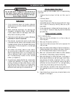
WHAt tO DO IF YOu sMeLL GAs
do not try to light any appliance.
•
do not use any electrical appliance.
•
do not touch any electrical switches; do not use
•
any phones in your building.
Immediately call your gas supplier from a neigh
-
•
bor’s phone. Follow the gas supplier’s instruc
-
tions. if you cannot reach your gas supplier, call
the fire department.
Should overheating occur or the gas supply fail
to shut off, do not turn off or disconnect the
electrical supply to the pump. Instead, shut off
the gas at a location external to the appliance
Do not use the boiler if any part of the gas con-
trol system has been underwater. A qualified
service technician should inspect the boiler
and replace any part of the control system and
any gas control which has been underwater.
Use only your hand to turn the gas control
knob. Never use tools. If the knob will not turn
by hand, don’t try to repair it. Force or attempt-
ed repair may result in a fire or explosion.
Electrical shock may cause serious injury or
death. The following procedures may expose
you to dangerous line voltage so use caution
to avoid touching live electrical contacts. All
service must be performed by a trained, experi-
enced service technician.
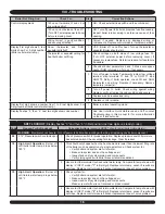
VIII - TROUBLESHOOTING
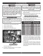
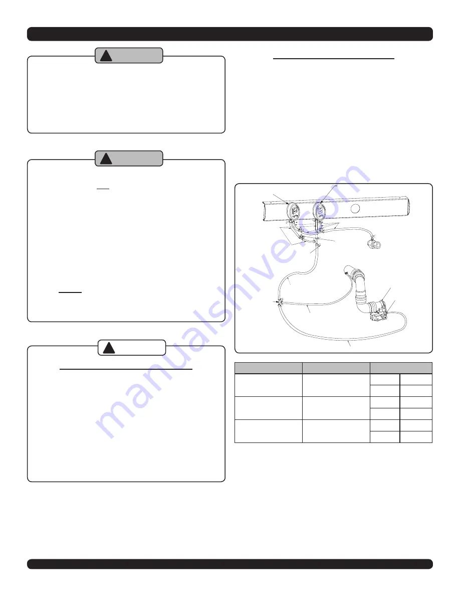
DIFFERENTIAL AIR PRESSURE
the differential air pressure switch is a safety device
which will prevent the boiler from firing if there is an air
intake, boiler heat exchanger or vent blockage.
To check the differential air pressure:
Turn off service switch or lower thermostat setting.
1.
Remove vinyl caps from tee.
2.
Install testing lines as shown to inclined manometer or
3.
differential pressure gauge with the ability to read 0.01”
increments to at least 6.0” w.c.
Turn on service switch and set thermostat to call for
4.
heat.
Boiler Status
Diff. Pressure
Switch Contacts
not running
0”
3.5”
Closed
0.14”
open
running with
Blockage
greater than or
equal to setpoints
3.5”
open
0.14”
Closed
Running w/out
Blockage (approx.)
Min. Fire: 0.3”
3.5”
Closed
Max. Fire: 2”
0.14”
Closed
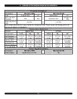
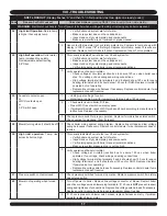
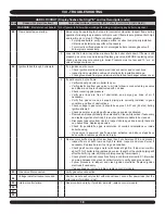
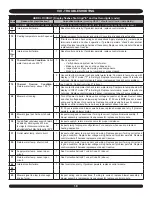
If manometer readings do not correspond to the chart above, check
for possible causes:
• Blockage or moisture in suction lines to switch.
• Blockage in air intake or vent pipes.
• Undersized air intake or vent pipes.
• Loose blower wheel on motor shaft.
• Incorrect pressure switch or pressure switch setpoint
When pressure reading is proper and the pressure switch is
operating properly, remove testing lines and reinstall vinyl caps to
tee and 3-way connector.
1500010 - SW PRESS NORM
OPEN SET PT .04”/0.14”
YELLOW LABEL
1552004 - TUBE, ORANGE,
3/16” X 5/16” OD SILICONE
1552004 - TUBE, ORANGE,
3/16” X 5/16” OD SILICONE
1230006 - CAP
BLK VINYL 3/16”
2 REQ’D
1552014 - TUBE
SILICONE, 3/16” ID
1500011 - SW PRESS NORM
CLOSED SET PT 3.5”
WHITE LABEL
GAS VALVE
PB-002.02 - ORIFICE PILOT
390686-1 HW-LP BBR10
1552004 - TUBE, ORANGE,
3/16” X 5/16” OD SILICONE
1552004 - TUBE, ORANGE,
3/16” X 5/16” OD SILICONE
1110001 - CLAMP ROTOR
HC-5ST-R, 22 REQ’D
AIR INLET
CONNECTION
151009 - TEE PLASTIC
BARBED HOSE, 3/16” ID
5 REQ’D
WARNING
!
WARNING
!
CAUTION
!


