9
4 - CONNECTING SUPPLY AND RETURN PIPING
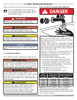
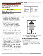
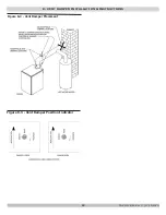
Figure 4-1 - Safety Relief Valve
WARNING
Burn and scald hazard. Safety relief valve could
discharge steam or hot water during operation.
Install discharge piping per these instructions. Failure
to follow these instructions could result in death or
serious injury.
!
Discharge line shall be installed to relief valve outlet
connection to avoid burns, scalding, or water damage due
to discharge of steam and/or hot water during operation.
Discharge line shall:
4.2 Safety Relief Valve Installation
See Figure 4-1
4.1 Connection Locations
• Boiler has one supply and one return tapping on each
side (4 total). Boiler supplied with dust caps only.
Remove all four (4) caps and plumb before filling
boiler with water.
• Supply and return may be piped to either side of
boiler, as desired.
•
Drain valve may be located off of unused return
tapping, as desired.
•
ASME relief valve may be located off unused
supply tapping IN UPRIGHT POSITION ONLY
.
• Unused supply and return tappings may be capped, as
desired. Relief valve and drain valve may be located
on near boiler piping using contractor supplied tees
with no valves.
Check local codes for maximum
distance from floor or allowable
safe point of discharge
.
RELIEF VALVE
On Opposite
side of supply
DISCHARGE
LINE
WARNING
Burn and scald hazard. Safety relief valve shall be
installed with spindle in upright position only,
following ASME BPV code. Failure to follow these
instructions could result in death or serious injury.
!
A. connect to relief valve outlet and piped down
to safe point of disposal. Check local codes for
maximum distance from floor or allowable safe
point of discharge.
B. be of pipe size equal to or greater than that of
the relief valve outlet over the entire length of
discharge line;
C.
have no intervening shutoff valve between safety
relief valve and discharge to atmosphere (do not
plug or place any obstruction in discharge line.
D. terminate freely to atmosphere where any
discharge will be clearly visible and at no risk of
freezing;
E. allow complete drainage of the valve and the
discharge line;
F. be independently supported and securely anchored
to avoid applied stress on the relief valve;
G. be as short and straight as possible;
H. terminate with plain end (not threaded);
I. be constructed of material suitable for exposure to
temperatures of 375° F (191°C); or greater.
J. Terminate freely to atmosphere where discharge is
clearly visible and no risk of freezing.
Refer to local codes and appropriate ASME Boiler
and Pressure Vessel Code for additional installation
requirements.
Alternate Location
Piped in Supply Line
(Contractor supplied
fittings)
Do Not Install
Pressure
Relief Valve
Horizontally
PN 240012785 Rev. C [11/15/2020]


