9
4 - CONNECTING SUPPLY AND RETURN PIPING
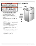
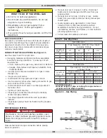
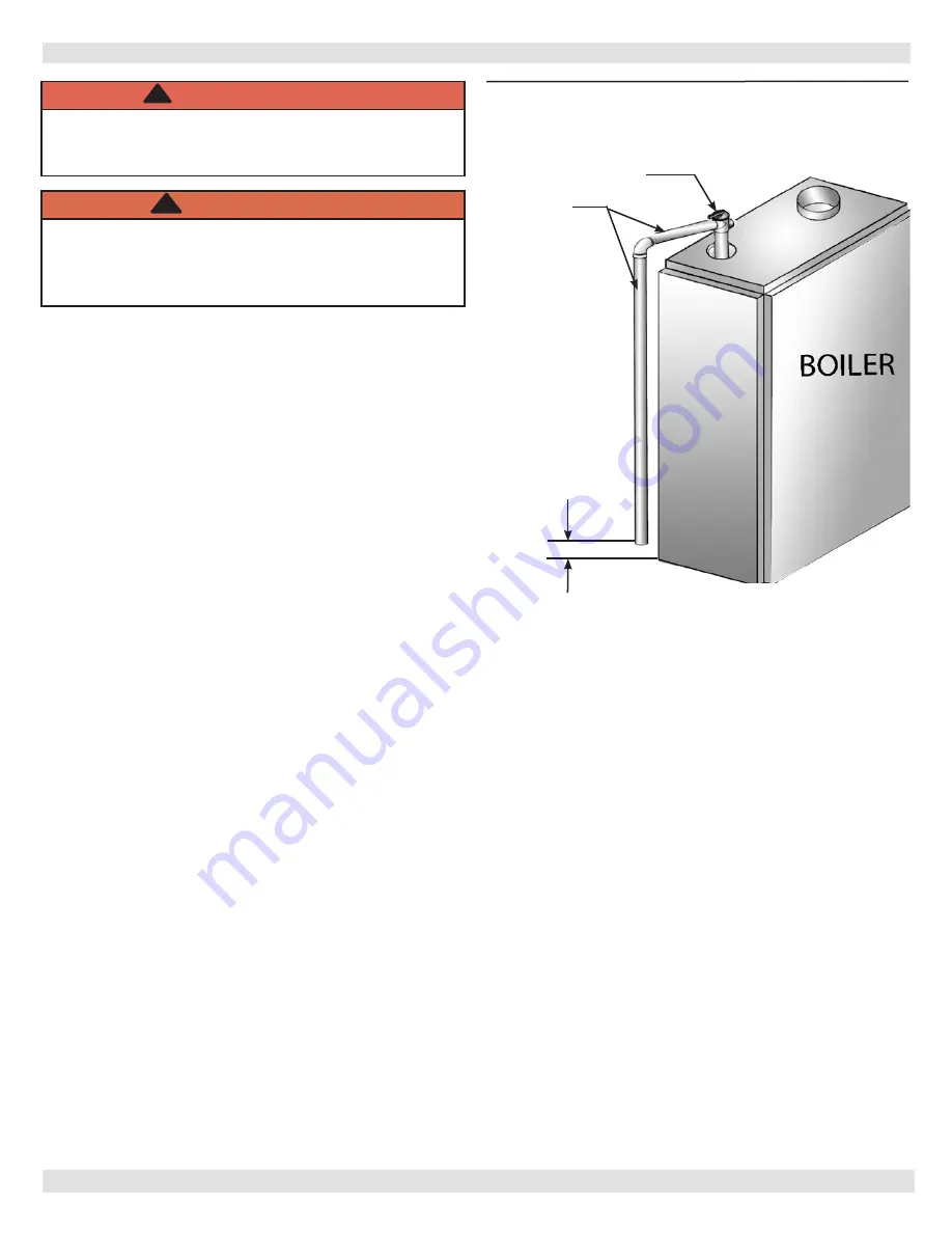
RELIEF VALVE
DISCHARGE
LINE
Check local
codes for
maximum
distance
from floor
or allowable
safe point of
discharge
.
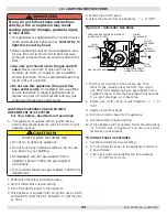
Figure 2 - Safety Relief Valve
1.
Refer to local codes and appropriate ASME Boiler
and Pressure Vessel Code for additional installation
requirements. Install safety relief valve using pipe
fittings provided with boiler. See Figure 2.
2.
Install safety relief valve with spindle in vertical
position.
3.
Do not install shutoff valve between boiler and safety
relief valve.
4.
Install discharge piping from safety relief valve. See
Figure 2.
• Use ¾” or larger pipe.
• Use pipe suitable for temperatures of 375°F (191°C)
or greater.
• Individual boiler discharge piping shall be independent
of other discharge piping.
• Size and arrange discharge piping to avoid reducing
safety relief valve relieving capacity below minimum
relief valve capacity stated on rating plate.
• Run pipe as short and straight as possible to location
protecting user from scalding and properly drain
piping.
• Install union, if used, close to safety relief valve outlet.
• Install elbow(s), if used, close to safety relief valve
outlet and downstream of union (if used).
• Terminate pipe with plain end (not threaded).
• Terminate freely to atmosphere where discharge is
clearly visible and no risk of freezing.
WARNING
Burn and scald hazard. Safety relief valve could
discharge steam or hot water during operation.
Install discharge piping per these instructions.
!
WARNING
Burn and scald hazard. Safety relief valve shall be
installed with spindle in upright position only,
following ASME BPV code. Failure to follow these
instructions could result in death or serious injury.
!
PN 240013087 Rev. A [09/30/2020]


