27
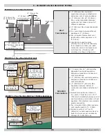
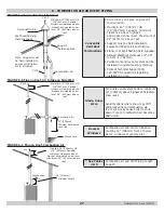
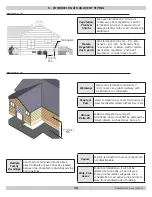
Concentric
Vent Roof
Terminations
Glue inner vent pipe to prevent
recirculation.
Maintain 12" (305mm) US
(18"(457mm) Canada) minimum
clearance above highest
anticipated snow level. Maximum of
24"(610mm) above roof.
Support must be field installed to
secure termination kit to structure.
Elbow, roof boot/flashing field supplied.
Allowed Wall/Roof thickness 1/2"-30"
(12.7mm - 762mm).
Vertical concentric vent system can be
installed in unused masonry chimney.
Contact Technical Support 800-
325-5479 for questions regarding
installation or use.
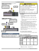
Combustion Air
Roof boot/flashing
(field supplied)
Support
(field supplied)
Combustion Air
Vent
Note: Support must
be field installed to
secure termination
kit to structure
Vent
Maintain 12"(305mm) US
(18"(457mm) Canada)
minimum clearance above
highest anticipated snow
level 24" (610mm) above
roof
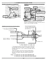
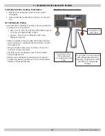
FIGURE 6-8 Flue on Roof, Air Intake on Side Wall
FIGURE 6-9 Flue on Roof, Combustion Air
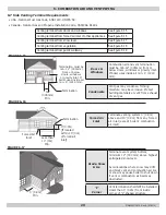
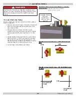
Grade, Snow
& Ice
Terminate vent system bottom, minimum
12" (305mm) above highest anticipated
snow level.
Avoid locations where snow may drift
and block vent and combustion air.
Ice or snow may cause boiler to shut
down if vent or combustion air becomes
obstructed.
Doors &
Windows
Combustion air and vent termination
must be 12" (305mm) from or below
doors, windows or gravity inlet.
* See Tables
4 & 5
Combustion air and Vent Piping Length
Page 23 .
FIGURE 6-7 Concentric Roof Terminal
6 - COMBUSTION AIR AND VENT PIPING
P/N# 240010615, Rev. E [07/2015]
Maintain 12"(305mm) US
(18"(457mm) Canada)
minimum clearance above
highest anticipated snow
level 24" (610mm) above
roof
Combustion Air
Vent
12" (305mm)
Minimum anticipated
snow line
Ground Level
Combustion
Air
Vent
24" (610mm)
* Minimum Length
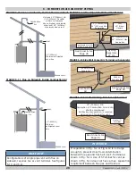
Maintain 12"(305mm) US
(18"(457mm) Canada)
minimum clearance above
highest anticipated snow level
maximum 24" (610mm) above
roof
Summary of Contents for SSV-050
Page 50: ...50 13 TROUBLE SHOOTING P N 240010615 Rev E 07 2015 ...
Page 52: ...52 13 TROUBLE SHOOTING P N 240010615 Rev E 07 2015 ...
Page 64: ...64 14 1 Connection Diagram 050 075 100 MBH 14 WIRING DIAGRAM P N 240010615 Rev E 07 2015 ...
Page 66: ...66 14 3 Connection Diagram 150 200 MBH 14 WIRING DIAGRAM P N 240010615 Rev E 07 2015 ...


