32
7.1 General
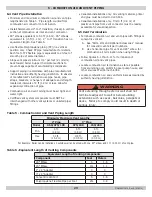
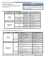
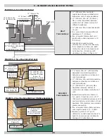
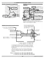
• Use piping materials and joining methods acceptable
to authority having jurisdiction. In absence of such
requirements:
• USA - National Fuel Gas Code, ANSI Z223.1/NFPA
54
• Canada - Natural Gas and Propane Installation Code,
CAN/CSA B149.1
•
Size and install gas piping system to provide sufficient
gas supply to meet maximum input at not less than
minimum supply pressure. See Table 8.
• Support piping with hooks straps, bands, brackets,
hangers, or building structure components to prevent or
dampen excessive vibrations and prevent strain on gas
connection. Boiler will not support piping weight.
• Use thread (joint) compound (pipe dope) suitable for
liquefied petroleum gas.
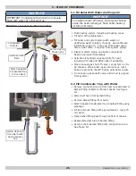
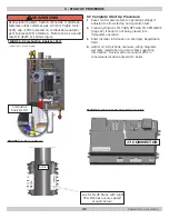
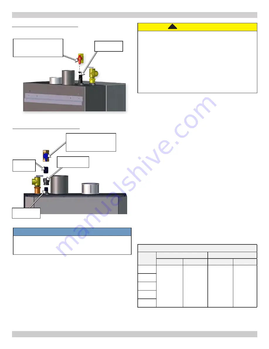
• Install manual main shutoff valve outside of jacket. See
figures 7-1A and 7-1B.
7.2 Conversion Kit Instructions
• See Gas Conversion Kit Instructions included with Boiler.
CAUTION
WHAT TO DO IF YOU SMELL GAS
• Do not try to light any appliance.
• Do not touch any electrical switch; do not use
any phone in your building.
• Immediately call your gas supplier from a
neighbor’s phone. Follow gas supplier’s
instructions.
•
If you cannot reach your gas supplier, call the fire
department.
!
Gas Supply Pressure
MODEL
Natural Gas
Propane
Min.
Max.
Min.
Max.
050
3.0" w.c.
(0.7 kPa)
13.5" w.c.
(3.3 kPa)
5.0" w.c.
(1.2 kPa)
13.5" w.c.
(3.4 kPa)
075
100
150
200
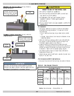
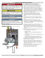
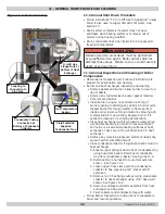
FIGURE 7-1A Gas Connection (at top of Boiler)
50/75/100 Shown
Note: See Glossary - Piping Table 14
NOTICE
Use two (2) wrenches when tightening boiler
fittings and pipes. Boiler's internal piping can be
damaged if subjected to excessive torque.
7 - GAS SUPPLY PIPING
Table 8 - Gas Supply Pressure
FIGURE 7-1B Gas Connection (at top of Boiler)
150/200 Shown
P/N# 240010615, Rev. E [07/2015]
Gas
Connection
Attach Supplied Gas
Shutoff Valve (shown
in open position)
Attach Supplied Gas
Shutoff Valve (shown
in open position)
Gas
Connection
1/2"x 3/4"
Increaser
3/4"
Nipple
Summary of Contents for SSV-050
Page 50: ...50 13 TROUBLE SHOOTING P N 240010615 Rev E 07 2015 ...
Page 52: ...52 13 TROUBLE SHOOTING P N 240010615 Rev E 07 2015 ...
Page 64: ...64 14 1 Connection Diagram 050 075 100 MBH 14 WIRING DIAGRAM P N 240010615 Rev E 07 2015 ...
Page 66: ...66 14 3 Connection Diagram 150 200 MBH 14 WIRING DIAGRAM P N 240010615 Rev E 07 2015 ...

