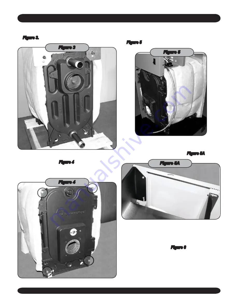
Attach pipe nipples to supply and return outlets. Be
4.
sure to use pipe dope before screwing into boiler. See
Figure 3.
Figure 3
Insert (4) 5/16” x 1/2” bolts into threaded holes on front
5.
of boiler as shown in
Figure 4
. Do not tighten down.
These bolts will hold the side Jacket panels on the
boiler.
Figure 4
Place the left side jacket panel on the 5/16”x1/2” bolts
6.
from step 6. Place the control panel on the top of the
boiler with the burner wire harness on the right. See
Figure 5
.
Figure 5
Attach the control panel to the left side jacket. The
7.
slot on the front of the control panel will slide over the
screw in the side jacket panel. See
Figure 5A
.
Figure 5A
Attach the right side jacket panel to the boiler and
8.
control panel like the left side. At the rear of the boiler,
be sure the panel fits over the top and bottom interme
-
diate flanges from step 2. Be sure to route the burner
wire harness as shown in
Figure 6
. Do not tighten all
the hardware yet.
2
KNOCKDOWN BOILER ASSEMBLY


