background image

Phone (828)323-8914

Fax

(828)323-8410

Email

sales@utilitysolutionsinc.com

Web

www.utilitysolutionsinc.com

101 33

rd

 Street Drive SE ·  Hickory, NC 28602

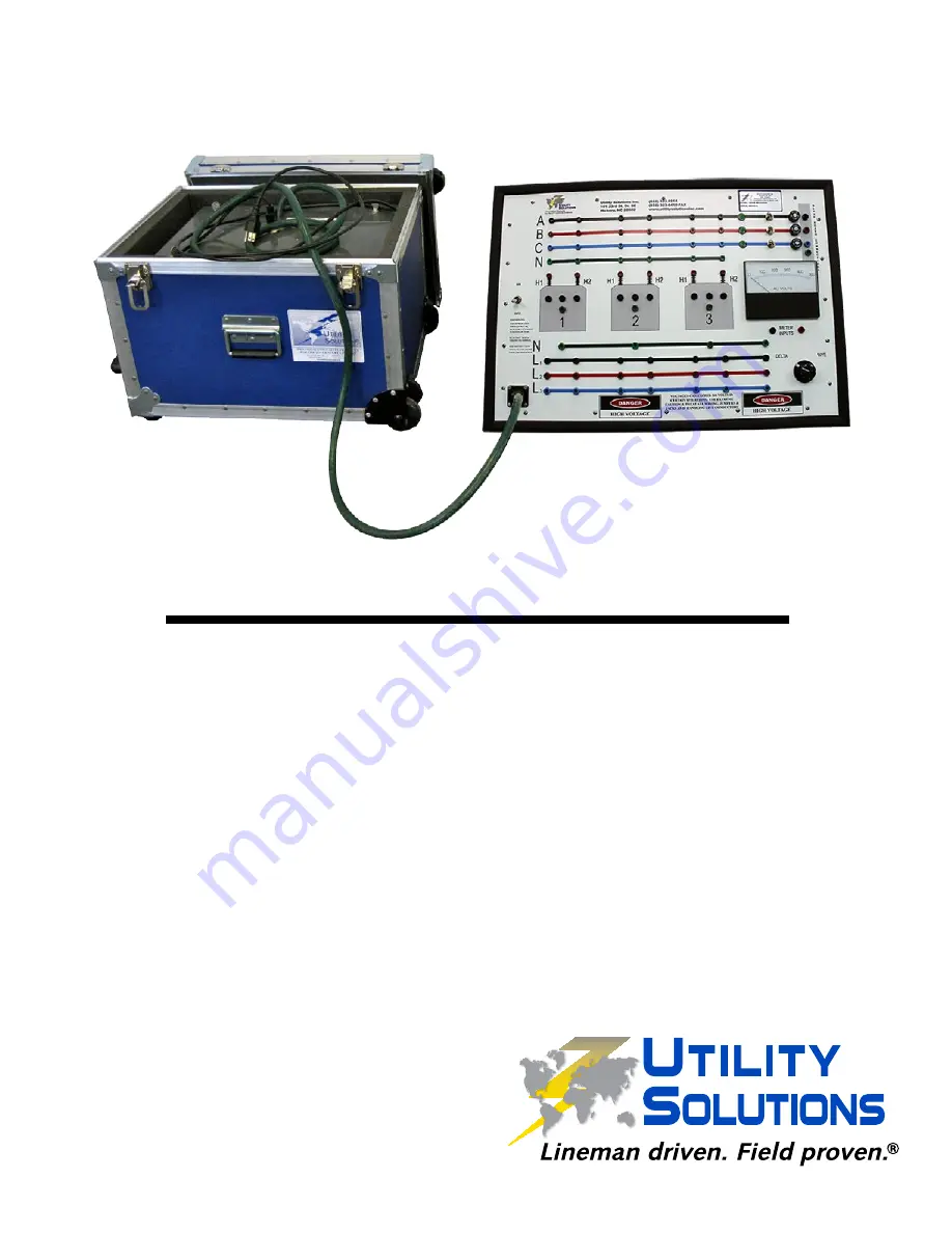
Load-Trainer

Transformer Simulator

XFMR-3BUSHING  Three Bushing Transformer Simulator

C-00879  XFMR-3BUSHING (11-11-15)

Operation Manual

Product Description   

2

Components  

3

Set-Up  

4

Simulator Description   

4

Front Panel Description 

  5

Toggle Switches   

6

Operation  

8

Examples  

8

Vector Application 


19

Transformer Backfeed   

19

Parallel Phases   

19

Polarity  

19

Polarity Example  

20

Warranty  

20

CONTENTS

Copyright © 2014 Utility Solutions, Inc.

Summary of Contents for XFMR-3BUSHING

Page 1: ...MR 3BUSHING Three Bushing Transformer Simulator C 00879 XFMR 3BUSHING 11 11 15 Operation Manual Product Description 2 Components 3 Set Up 4 Simulator Description 4 Front Panel Description 5 Toggle Switches 6 Operation 8 Examples 8 Vector Application 19 Transformer Backfeed 19 Parallel Phases 19 Polarity 19 Polarity Example 20 Warranty 20 CONTENTS Copyright 2014 Utility Solutions Inc ...

Page 2: ...this device to rain moisture or combustible materials Select a place that is level dry and between 41 F and 95 F Do not place either unit on a heat generating object Avoid a dusty place or a place subject to vibrations The power cord supplied is configured and rated for standard 120 Volt 10 Amp receptacles It is to be used as a disconnect for this device by unplugging the power cord from the recep...

Page 3: ...TIONAL THREE BUSHING FRONT PANEL XFMR 4BUSHING PRL ADDITIONAL FOUR BUSHING FRONT PANEL Front Panel Power Supply Multiple conductor Cord Shipping Cases Power Cord Patch Cords Qty Description 1 Front Panel Large Shipping Case 1 Power Supply Small Shipping Case 1 Multiple conductor cord with polarized plug Green 1 120 Volt AC Power Cord Black 8 12 red pin patch cords 3 12 black pin patch cords 4 4 bl...

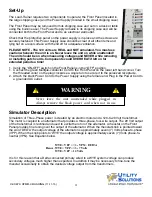
Page 4: ...case and the Power Supply located in the small shipping case The Front Panel may be removed from its shipping case and set on a desk or table using the built in easel The Power Supply remains in its shipping case and will be connected both to the Front Panel and to an electrical wall outlet Check that the protective panel on the power supply is in place and the screws are securely fastened This Po...

Page 5: ...lines in the middle of the Front Panel use red input terminals H1 and H2 which connect to actual transformers located behind the panel These connections are made using the Pin Patch Cords small metal ends The plugs can be stacked if desired Transformer Outputs Each transformer has three black unlabeled output terminals They can be thought of as X1 X2 and X3 from right to left respectively where X2...

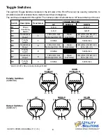
Page 6: ...B C A B B S3 Transformer Ouput 1 120 v X3 X2 No Output X2 X1 Open secondary 120 v X3 X2 X2 X1 240 v X3 X1 S4 Polarity Switch 1 Additive Subtractive S5 Transformer Ouput 2 120 v X3 X2 No Output X2 X1 Open secondary 120 v X3 X2 X2 X1 240 v X3 X1 S6 Polarity Switch 2 Additive Subtractive S7 Transformer Ouput 3 120 v X3 X2 No Output X2 X1 Open secondary 120 v X3 X2 X2 X1 240 v X3 X1 S8 Polarity Switch...

Page 7: ...UP 120 X1 X2 CTR 0 DN 240 X1 X3 UP ABC DN ABB S1 S2 Both DN BBB Transformer 1 UP Additive Polarity DN Subtractive Polarity Transformer 2 UP Additive Polarity DN Subtractive Polarity Transformer 3 UP Additive Polarity DN Subtractive Polarity Normal position of all switches is UP toward the top of the unit Left Side of Front Panel FIGURE 1 Toggle Switches S2 S4 S6 S8 S1 S3 S5 S7 ...

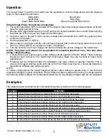
Page 8: ...uced after the installation has been shown to operate correctly This is done by the toggle switches on the left side of the Front Panel see Figure 1 and at the instructors discretion to simulate real world scenarios NOTE In certain configurations the actual measured device output voltage is greater than or less than the expected voltage for a given simulation The AC Meter has been scaled at the fa...

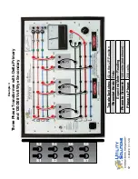
Page 9: ...Transformer with Delta Primary and 120 Volt Wye Secondary Example 1 Toggle Switches All in the UP Position Rheostat Knob Delta Expected Meter Reading Phase to Ground 120 volts Phase to Phase 0 volts not shown S2 S4 S6 S8 S1 S3 S5 S7 ...

Page 10: ...Transformer with Delta Primary and 120 Volt Delta Secondary Example 2 Toggle Switches All in the UP Position Rheostat Knob Delta Expected Meter Reading Phase to Ground 0 volts not shown Phase to Phase 120 volts S2 S4 S6 S8 S1 S3 S5 S7 ...

Page 11: ...Primary and 120 240 Volt Delta Secondary Example 3 Toggle Switches 3 5 or 7 DOWN whichever corresponds to the Transformer in use Rheostat Knob Delta Expected Meter Reading Phase to Ground 120 volts not shown Phase to Phase 240 volts S2 S4 S6 S8 S1 S3 S5 S7 ...

Page 12: ...nsformer with Delta Primary and 120 208 Volt Wye Secondary Example 4 Toggle Switches All in the UP Position Rheostat Knob Delta Expected Meter Reading Phase to Ground 120 volts not shown Phase to Phase 208 volts S2 S4 S6 S8 S1 S3 S5 S7 ...

Page 13: ...ransformer with Delta Primary and 120 Volt Delta Secondary Example 5 Toggle Switches All in the UP Position Rheostat Knob Delta Expected Meter Reading Phase to Ground 0 volts not shown Phase to Phase 120 volts S2 S4 S6 S8 S1 S3 S5 S7 ...

Page 14: ...lta Primary and 120 240 Volt High Leg B Delta Secondary Example 6 Toggle Switches 3 5 and 7 DOWN Rheostat Knob Delta Expected Meter Reading Phase to Ground L 1 120 volts shown L 2 208 volts L 3 120 volts Phase to Phase 240 volts S2 S4 S6 S8 S1 S3 S5 S7 ...

Page 15: ...ormer with Open Delta Primary and 120 Volt Open Delta Secondary Example 7 Toggle Switches All in the UP Position Rheostat Knob Delta Expected Meter Reading Phase to Ground 0 volts not shown Phase to Phase 120 volts S2 S4 S6 S8 S1 S3 S5 S7 ...

Page 16: ... Transformer with Wye Primary and 120 Volt Delta Secondary Example 8 Toggle Switches All in the UP Position Rheostat Knob Wye Expected Meter Reading Phase to Ground 0 volts not shown Phase to Phase 120 volts S2 S4 S6 S8 S1 S3 S5 S7 ...

Page 17: ...ransformer with Wye Primary and 120 208 Volt Wye Secondary Example 9 Toggle Switches All in the UP Position Rheostat Knob Wye Expected Meter Reading Phase to Ground 120 volts not shown Phase to Phase 208 volts S2 S4 S6 S8 S1 S3 S5 S7 ...

Page 18: ...nsformer with Wye One Leg Out Primary and 120 Volt Open Delta Secondary Example 10 Toggle Switches 3 and 5 DOWN Rheostat Knob Wye Expected Meter Reading Phase to Ground 0 volts not shown Phase to Phase 240 volts S2 S4 S6 S8 S1 S3 S5 S7 ...

Page 19: ...ye one leg out Open Delta see Example 10 to become energized from the same phase In most instances a jumper on a vertical corner burning into and falling down on the phase below has caused this If the bank is connected between these phases this results in the input windings being in parallel and the output windings still connected in series Using normal procedures this produces a situation that is...

Page 20: ...ple 5 and measure voltage across L1 and L2 This time change the position of two Additive Subtractive switches 6 and 8 from Up to Down simultaneously What happens Why Turn off power The results are the same as if we changed only switch 4 The reason is the same Now without doing anything else move switch 4 from Up to Down Turn on the power and observe the voltmeter What happens It would appear as if...

Reviews: