background image

Page 7


UTS SALES & REPAIRS LTD


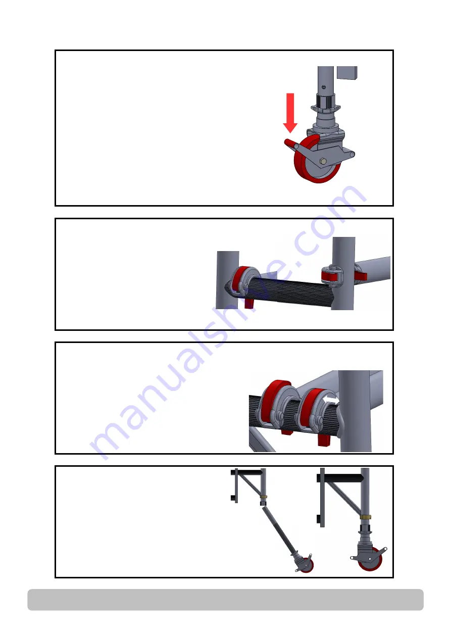
LOCKING CASTORS


Castor wheels should be pointed outwards 
at approximately 45 degrees and locks en-
gaged as shown opposite.


FITTING STABILISERS


Attach a stabiliser to each corner of the 
tower at approximately 45 degrees for max-
imum stability (refer to relevant illustrations) 
and attach the clamps where indicated.


On the S2 stabiliser use the telescopic leg 
for adjustment on uneven ground.


Make sure that all stabilisers are firmly in 
contact with the ground when using the 
structure.


CORRECT FITTING OF 
HORIZONTAL BRACING


THE CORRECT FITTING OF 
HORIZONTAL BRACING IS IMPORTANT.


The diagrams opposite illustrate the 
CORRECT brace positions.


REMEMBER: Always fit braces 
DOWNWARD or from the inside facing 
OUTWARD –


BUT NEVER INWARD


FITTING ADJUSTABLE LEGS


Take the adjustable leg assembly complete 
with its castors, make sure that all the 
adjusting nuts are positioned down at the 
castor and slide them into the vertical tube, 
turn the base unit the right way up and with 
the aid of a spirit level placed on the 
platform, the adjusting nuts can be used to 
level the structure. (and not to gain 
additional height).


BRACE CLAMP LOCKING


Ensure that the brace clamp is locked as 
shown. 


Always make sure the brace is not clamped 
too close to the weld as indicated by the 
arrow on the drawing on the right.


Un

-

Locked


Locked


Summary of Contents for 1450/850

Page 1: ...l should be qualified or competent to erect this tower Please consult the PASMA s code of practice for full information on the use of Mobile Access Towers Remember to do a risk assessment of the area...

Page 2: ...UTS LADDER 1450 850 INSTRUCTION MANUAL Page 2...

Page 3: ...nce 6 Components and Weights 8 Assembly 9 Dismantling 16 Configurations and Weights 17 Risk Assessment Form 19 UTS LADDER 1450 850 Instruction Manual Mobile Access Tower UTS SALES REPAIR UNIT 1A CANTE...

Page 4: ...drail braces for the level above the platform NEVER STAND ON AN UNGUARDED PLATFORM Before assembly or erection of this Mobile Access Tower MAT please ensure that A risk assessment has been done and al...

Page 5: ...and only from the base Beware of overhead obstructions live wires hanging apparatus or other objects Do not move with people or material on the tower Do not move the assembled MAT if wind speeds exce...

Page 6: ...pended as a complete structure Always keep this instruction manual safe Broken damaged or incorrect components must never be used The equipment shall be quarantined and assessed for replacement repair...

Page 7: ...ING OF HORIZONTAL BRACING IS IMPORTANT The diagrams opposite illustrate the CORRECT brace positions REMEMBER Always fit braces DOWNWARD or from the inside facing OUTWARD BUT NEVER INWARD FITTING ADJUS...

Page 8: ...me 5 4 11 1 8m Horizontal Brace 2 1 4 1m Span Frame 4 12 2 1m Diagonal Brace 2 2 5 1 5m Ladder Frame 8 13 Complete Toe Board Set 8 6 1 5m Span Frame 5 6 14 S1 Stabiliser 4 1 7 2m Ladder Frame 10 4 15...

Page 9: ...frame never the outside When working on the platform never overreach The end frames should provide a firm hand hold Insert adjustable leg assembly with castors or base plates into the base of ladder f...

Page 10: ...fig 3 and lock the locking clips refer to page 6 Attach diagonal braces on both sides from the 1st rung to the 3rd rung of the structure in opposing directions Place a trap door platform on the 1st ru...

Page 11: ...page 16 Climb the ladder and from a protected through the trapdoor position attach horizontal guardrail braces to the 5th and then 6th rungs on both sides of the platform Never climb onto a platform t...

Page 12: ...UTS LADDER 1450 850 INSTRUCTION MANUAL Page 12 Attach 2nd pair of diagonal braces following on from the previous ones Attach the next 4 rung frames and lock clips as per fig 6 6...

Page 13: ...the tower at this height 4m continue with step 8 When building beyond this level repeat steps 4 5 and 6 until desired level is achieved then complete the tower with steps 8 and 9 Reuse the trap door p...

Page 14: ...per fig 7 The 1st rung trap door platform should be moved up to the 8th rung the fixed platform can now be fitted alongside it LOCK WIND LOCKS Climb up the ladder and from a protected through the tra...

Page 15: ...TS SALES REPAIRS LTD Fit toe boards to all working platforms see instructions on page 4 5 9 Maximum distance between platforms should not exceed 2 25m Maximum distance to first platform should not exc...

Page 16: ...h one stabiliser to each corner of tower at approx 45 degrees The bottom clamp should be fitted as low as possible refer to the diagram opposite Ensure that all four rubber feet are in contact with th...

Page 17: ...2 7m Diagonal Brace 2 3 13 Folding Toe Board Set 1 1 Instruction Manual 1 1 S1 Stabiliser 4 4 4 4 4 4 4 4 4 4 4 4 4 S2 Stabiliser Approx Tower Shelf weight Kgs 1 8m 74 2 81 2 101 4 121 5 136 8 143 8...

Page 18: ...Brace 6 6 2 1m or 2 7m Diagonal Brace 2 3 13 Folding Toe Board Set 1 1 Instruction Manual 1 1 S1 Stabiliser 4 4 4 4 4 4 4 4 4 4 4 4 4 S2 Stabiliser Approx Tower Shelf weight Kgs 1 8m 85 92 7 113 119 4...

Page 19: ......

Page 20: ...TION MANUAL Page 20 UTS SALES REPAIRS LTD UNIT 1A CANTERBURY INDUSTRIAL PARK ISLAND ROAD HERSDEN CANTERBURY KENT CT3 4HQ TEL 01227 860085 WWW TOWERSANDPODIUMS CO UK KM 617169 Document No CM085 Version...

Reviews: