31
Weitere Montage
4.
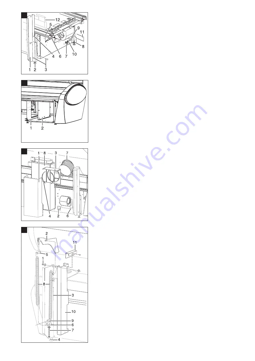
Schieben Sie den Kopf der Schraube
DIN 933 M 6 x 20 (40/6) in der Nut (40/5)
so weit Richtung Gerätemitte bis der
Schaft der Schraube in der schlitzförmigen
Aussparung (40/4) des Trägers sitzt.
5.
Sichern Sie die Schraube (40/6) durch
Unterlegscheibe und Mutter.
6.
Drehen Sie die 4 Zylinderschlitzschrauben
6 x 20 (40/3) mit je einer Unterlegscheibe
zur Befestigung des Kinematikträgers ein.
Unbedingt fest anziehen!
7.
Befestigen Sie ebenso den zweiten
Kinematikträger.
8.
Justieren Sie die fünf Stellfüsse (40/2)
entsprechend Ihren Fußbodengegeben-
heiten.
Das Fußgestell muss waagerecht
stehen.Mindestabstand Fußgestell-
rahmen – Boden 20 mm.
9.
Drehen Sie die Stellfüsse unbedingt mit
Mutter M 10 (40/8) und Scheibe gegen
das Fußgestell fest.
10. Überprüfen Sie, ob die Abschottwand
(41/2) in der Zwischenwand des Fußgestell
montiert ist, wenn Sie das Gerät
ohne Klimagerät
betreiben.
11. Montieren Sie den oberen Teil des Kamins
„Anschluss Warmluftrückführung“ (42/8),
falls sie ihn vorher demontiert haben.
9.2.8 Fluter montieren
1.
Legen Sie den Fluter auf die Liege, die Sie
vorher mit Styropor oder Kantholz an der
vorderen Kante abgedeckt haben.
2.
Führen Sie den Bolzen (43/2) mit der Halte-
rung des Fluters in den Kinematikträger
(43/3) ein und schrauben diesen mit den
Scheiben und der selbstsichernden Mutter
(43/1) fest.
Die Fluterhalterung mit Bolzen (43/2) und
Unterlegscheibe muß zwischen den 2
Halterungen des Kinematikträgers (43/3)
eingehängt sein.
Unbedingt fest anziehen!
3.
Bringen Sie den Fluter in seine oberste
Stellung und befestigen Sie die Zugfedern.
Hängen Sie die Zugfedern 43/8) in den
oberen Bolzen (43/5) ein.
4.
Hängen Sie die Zugfedern in den unteren
Bolzen (43/9) ein.
5.
Schrauben Sie die Schraube (43/7) durch
die Halterung (43/6) am Kinematikträger
(43/3) und den unteren Bolzen (43/9).
Verfahren Sie ebenso mit dem kopfseitigen
Kinematikträger.
6.
Ziehen Sie die Schraube (43/7) an beiden
Kinematikträgen gleichmäßig an.
Die Zugfedern werden so vorgespannt, bis
der Fluter bei jedem Öffnungswinkel in
der Schwebe bleibt.
7.
Montieren Sie die Abdeckung (43/10) und
dann die Abdeckung (43/11) an den
Kinematikträgern.
8.
Ziehen Sie die drei Fluterkabel und das
Innenbedienkabel durch den Deckel
(42/3) des Anschlusskamins.
9.
Schlagen Sie den Schlauch (42/7) über den
Befestigungsrand des Deckels ein und
befestigen Sie den Schlauch mit der
Schlauchschelle (42/4).
Further installation
4.
Push the head of the screw DIN 933
M 6 x 20 (40/6) in the groove (40/5) to-
wards the centre of the unit until the shank
of the screw is sitting in the slotted recess
(40/4) in the holder.
5.
Secure the bolt (40/6) with a nut and
washer.
6.
Screw in the 4 slotted cylinder head screws
6 x 20 (40/3) with one washer each to
fix the kinematics holder.
Make sure they are tightened.
7.
Mount the second kinematics holder in the
same way.
8.
Adjust the five feet (40/2) according to floor
conditions.
The base must be horizontal. Minimum
spacing base frame – floor 20 mm.
9.
Tighten the feet against the base with an
M 10 nut (40/8) and washer.
10. Check whether the shielding panel (41/2)
in the intermediate wall of the base is
mounted when the unit is operated
without an air conditioning unit.
11. Mount the upper part of the chimney
“connection warm air recirculation”
(42/8) with six screws 4.2 x 9.5 if you have
dismantled it beforehand.
9.2.8 Assembling the Canopy
1.
Place the canopy on the bed which you
have covered before with polystyrene or
squared timber at the front edge.
2.
Insert the bolt (43/2) with the canopy
mounting into the cinematic support
(43/3) and tighten it with the discs and the
self-locking nut (43/1).
The canopy mounting with bolt (43/2) and
washer must be suspended between the
2 mountings of the cinematic support
(43/3).
Fix tightly!
3.
Raise the canopy to its highest position and
fasten the springs. The springs (43/8)
must be suspended from the upper bolt
(43/5).
4.
Then fix the springs at the lower bolt
(43/9).
5.
Screw the screw (43/7) through the
mounting (43/6) of the cinematic support
(43/3) and the lower bolt (43/9).
Proceed the same way with the cinematic
support at the upper side.
6.
Tighten the screw (43/7) evenly at both
cinematic supports.
The springs are pretensioned in such a way
that the canopy remains suspending at
each aperture angle.
7.
Mount the cover (43/10) and then the cover
(43/11) of the cinematic support.
8.
Take the three canopy cables and the
internal operating cable and pull these
through the the cover (42/3) of the
connection channel (42/1).
9.
Pull the hose (42/7) over the connecting
union of the cover and fix it with the hose
clip (42/4).
40
41
Gerät ohne Klimagerät
Only unit without air conditioning unit
42
43
Wichtig! / Important!


