37
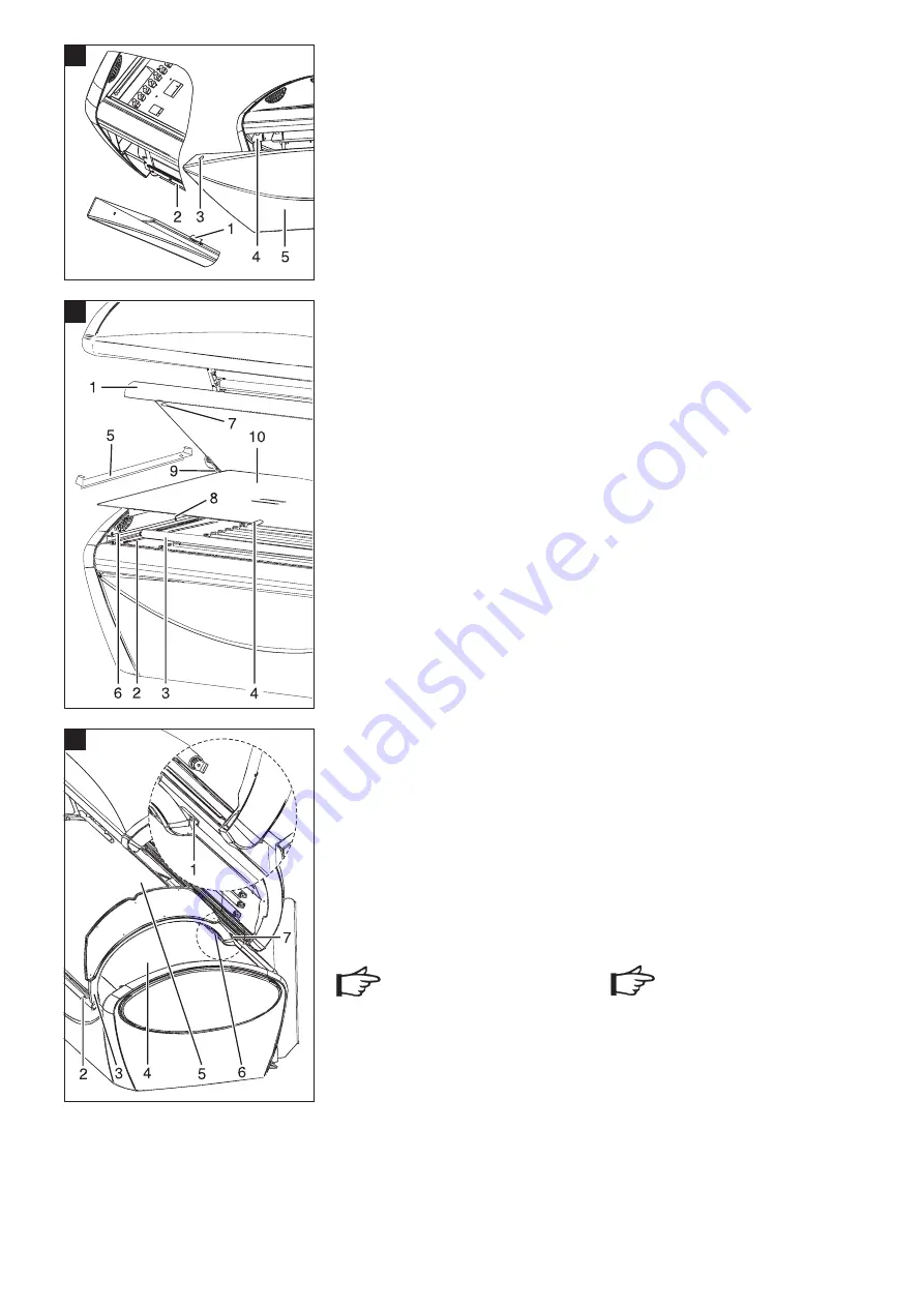
Grosse Abdeckhaube vor dem Fußgestell
montieren
1.
Führen Sie die große Abdeckhaube (61/5)
von vorne her parallel zum Fußgehäuse an
dasFußgehäuse heran.
2.
Hängen Sie zuerst die unteren Haken (61/1)
der Abdeckhaube über die Halterungen
(61/2) des Fußgestells und kippen Sie die
Abdeckhaube oben gegen das Fußgestell.
Die oberen Langlöcher (61/3) der Abdeck-
haube rasten in die Aufnahmen (61/4) des
Fußgestells ein.
9.3.1 Montage Liege
Liege montieren
1.
Stellen Sie beide Lampenabdeckungen
(62/6) auf den Fassungsträger. Die Schrau-
benköpfe M 6 x 10 des Fassungsträger-
blechs tauchen dabei in die Bohrungen
(Durchmesser 12 mm) der Lampenab-
deckung (62/6) ein.
Gerät ohne Klimagerät: Stellen Sie die
Lampenabdeckung mit Filtermatte kopf-
seitig auf.
2.
Legen Sie die flache Acrylglasscheibe
(62/10) mit dem Griffloch nach vorne
zwischen die Schrauben (62/8) der Lampen-
abdeckung.
3.
Stellen Sie die beiden Abdeckwinkel (62/5)
mit ihren Langlöchern über die Schrauben-
köpfe der darunter liegenden Lampenab-
deckwinkel (62/6).
4.
Nehmen Sie zu zweit, jeder auf einer Stirn-
seite, die Liegenplatte (62/1) auf und halten
Sie diese so über die Liege, dass ihre vordere
Längsseite nach oben geklappt ist.
5.
Führen Sie die Liegenplatte mit ihrem hin-
teren Aluprofil (62/9) in das Alu-Längsprofil
der Liege ein.
6.
Kippen Sie die Liegenplatte vorne nach unten
bis sie auf der Liege liegt.
7.
Drehen Sie die Schlitze der Riegel (62/7)
horizontal.
9.3.2 Montage Fluterrahmen
Innenfluter einhängen
1.
Hängen Sie den Innenfluter (63/3) mit seinen
Halterungen (63/7) in das hintere Fluter-
längsprofil ein und kippen Sie ihn mit seiner
vorderen Längsseite auf die Liege.
2.
Stecken Sie den Stecker in das Innenbe-
dienpanel (63/6).
3.
Kippen Sie den Innenfluter gegen den Fluter
und drehen Sie die drei Innensechskantriegel
(63/2) mit dem Innensechskantschlüssel
herum.
Der Innenfluter ist fixiert.
9.4 Anschluss der Geräteabluft
Achtung!
Wichtiger Hinweis!
Führen Sie die erwärmte Kühlluft nur über eine
direkte Luftabführung (Zentralabluft) vom Ab-
luftkanal des Gerätes ab.
Schließen Sie deshalb auf den Schlauchad-
apter unbedingt einen Abluftschlauch an, mit
dem Sie die Abluft nach außen führen.
uwe empfiehlt als Standardweiterführung einen
speziellen Abluftkamin, den Sie als Zubehör
bestellen können.
Weitere Informationen über eine effektive Be-
und Entlüftung entnehmen Sie aus der bei Ihrem
Händler oder bei uns erhältlichen
Broschüre „KLIMATIPPS“.
Mounting the large covering panel in front of
the base
1.
Insert the large covering panel (61/5) from
the front parallel to the base.
2.
First hang the lower hooks (61/1) of the
covering panel over the retainers (61/2) of
the base and rotate the top covering panel
downwards completely onto the base. The
upper oblong holes (61/3) on the covering
panel lock into the sockets (61/4) in the
base.
9.3.1 Fitting the Bed
Fitting the bed
1.
Place the two lamp covers (62/6) on the
socket carrier.
The M 6 x 10 screw heads of the socket
carrier sheet fit into the holes (12 mm dia.)
in the lamp cover (62/6).
Models without air conditioning: Place the
lamp cover with filter mat at the face
end of the sun bed.
2.
Place the flat acrylic panel (62/10) with the
grip hole to the front between the screws
(62/8) of the lamp cover.
3.
Place the two brackets (62/5) with their slot
holes over the screw heads of the lamp
brackets (62/6).
4.
With one person at each end, pick up the
bed panel (62/1) and hold it over the bed
so that the front longitudinal side is raised
upwards.
5.
Guide the rear edge of the bed panel with its
aluminium profile (62/9) into the
longitudinal aluminium profile of the bed.
6.
Lower the front of the bed panel until it rests
on the bed.
7.
Turn the slot of the bolts (62/7) to the
horizontal position.
9.3.2 Fitting the Canopy Frame
Fitting the interior canopy
1.
Fit the interior canopy with its brackets
(63/7) into the rear canopy longitudinal
profile and lower its front longitudinal side
onto the bed.
2.
Connect the plug to the interior control board
(63/6).
3.
Lower the interior canopy towards the
canopy and turn the three hexagonal bolts
(63/2) with the Allen key.
The interior canopy is fixed.
9.4 Connecting the air extraction unit
ATTENTION!
The heated cooling air must be extracted
through a direct air outlet (central air extrac-
tion) from the air extraction duct of the unit.
A tube must therefore be attached to the air
extraction adapter to remove the extracted air
to the outside.
For this purpose, uwe recommends a
specially designed air extraction flue which
can be ordered as an accessory.
Further information on effective ventilation is
given in the brochure “ Ventilation Tips”, avai-
lable from your authorized dealer or direct from
uwe.
Wichtig!
Important!
61
62
63
61


