background image

Installation Instructions, Viper 2000 Control System

PRD0167E01en

UWE Verken AB

4(6)

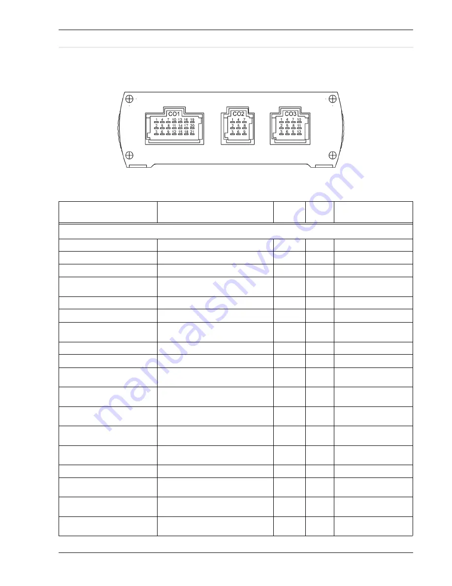
C o n n e c t i o n   o f   c o m p a r t m e n t   u n i t   ( s y s t   1 )

Connections to components should be performed according to 
the table below:

Table 2: Compartment unit

Description

Comment

See 
footnote

Pin

Type

Valve, Flap & analog in CO1 21 pole

Valve, Convector circuit pos. feedb.

Open = High Voltage

2) ,4) 

CO1:1

Analog 0 - 33V

Temp sensor GND, Compartment

CO1:2

Sensor ground

Temp sensor, Compartment

CO1:3

Analog NTC 4,7k

Valve, Ventilation circuit

Open = 24V. Direct Drive / Motor valve 
driver.  Non-inverted

2) 

CO1:4

Solid state outp. 1.9A

Temp sensor GND, feed water

CO1:5

Sensor ground

Temp sensor, feed water

CO1:6

Analog NTC 4,7k

Valve, Ventilation circuit

Open = 0V. Direct Drive / Motor valve driver. 
Inverted

2) 

CO1:7

Solid state outp. 1.9A

Temp sensor GND, Ventilation air

CO1:8

Sensor ground

Temp sensor, Ventilation air

CO1:9

Analog NTC 4,7k

Valve, Convector circuit

Open = 24V. Direct Drive / Motor valve 
driver.  Non-inverted

2) 

CO1:10

Solid state outp. 1.9A

Valve, Convector circuit

Open = 0V. Direct Drive / Motor valve driver.  
Inverted

2) 

CO1:11

Solid state outp. 1.9A

Flap Fresh/Rec, Vent air pos feedb.
Left side

1) ,4) 

CO1:12

Analog 0 - 33V

Flap Fresh/Recirc, Ventilation air 
Right side

Rec = +24V. Source / sink

CO1:13

Solid state outp. 1.9A

Flap Fresh/Recirc, Ventilation air 
Right side

Rec = 0V. Source / sink

CO1:14

Solid state outp. 1.9A

Valve, Ventilation circuit pos feedb.

Open = High Voltage

2) ,4) 

CO1:15

Analog 0 - 33V

Flap Fresh/Recirc, Ventilation air Left 
side

Rec = +24V. Source / sink

CO1:16

Solid state outp. 1.9A

Flap Fresh/Recirc, Ventilation air Left 
side

Rec = 0V. Source / sink

CO1:17

Solid state outp. 1.9A

Flap Fresh/Rec, Vent air pos feedb. 
Right side

Recirc= High voltage

1) ,4) 

CO1:18

Analog 0 - 33V

Summary of Contents for Viper 2000

Page 1: ...ferably in a way that a minimum of sunlight is reflected in the display To mount the sensors see separate installation sheet PRD0070 Ensure that the control units are placed at a place pro tected from water Structure of the control system Example of structure in an articulated bus Drivers place Climate zone 1 Climate zone 2 Drivers place temperature Outside temperature Defroster temperature Flap F...

Page 2: ...sensor Defroster air CO1 5 Analog NTC 4 7kΩ Valve Defroster circuit position feed back Open High Voltage 2 4 CO1 6 Analog 0 33V Flap Fresh Recirc defroster air Rec 24V Source sink CO1 7 Solid state outp 1 9A Valve Driver s Convector circuit pos feedback Open High Voltage 2 4 CO1 8 Analog 0 33V Temp sensor GND defroster air CO1 9 Sensor ground Flap Fresh Recirc defroster air Rec 0V Source sink CO1 ...

Page 3: ...ster fan speed 3 Relay driver output CO2 5 Solid state outp 1 9A AC OverTemp 5V Compr over tmp CO2 6 Digital input AC Condenser fan Contactor driver CO2 7 Solid state outp 2 2A Defroster fan speed 1 Relay driver output CO2 8 Solid state outp 1 9A Defroster fan speed PWM 20 kHz Duty Cycle modulated differential output for direct interface with PWM switch NonInv CO2 9 EIA RS485 transmitter out put 1...

Page 4: ...O1 7 Solid state outp 1 9A Temp sensor GND Ventilation air CO1 8 Sensor ground Temp sensor Ventilation air CO1 9 Analog NTC 4 7kΩ Valve Convector circuit Open 24V Direct Drive Motor valve driver Non inverted 2 CO1 10 Solid state outp 1 9A Valve Convector circuit Open 0V Direct Drive Motor valve driver Inverted 2 CO1 11 Solid state outp 1 9A Flap Fresh Rec Vent air pos feedb Left side 1 4 CO1 12 An...

Page 5: ...olid state outp 1 9A AC Lp In series with Clutch activation CO2 3 Digital input Vent fan speed 1 Relay driver output CO2 4 Solid state outp 1 9A AC OverTemp 5V Compr over tmp CO2 5 Digital input AC Hp In series with Clutch activation CO2 6 Digital input AC Condenser fan Contactor driver CO2 7 Solid state outp 2 2A AC Compr Clutch Direct drive CO2 8 Solid state outp 5 7A AC Ice detection 5V Ice CO2...

Page 6: ...drive capability is a hardware option that can be delivered on request Since no single input pin can carry a load of more than 10A additional Batt connections has to be done 6 If no high current drivers are used only one of these outputs need to be used If only one high curren driver is used two of these has to be connected and if two or more are used all three supply pins should be connected AMP ...

Reviews: