background image

5

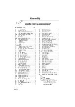
Assembly

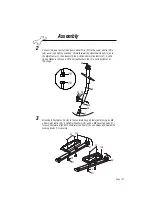
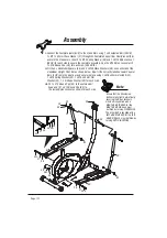
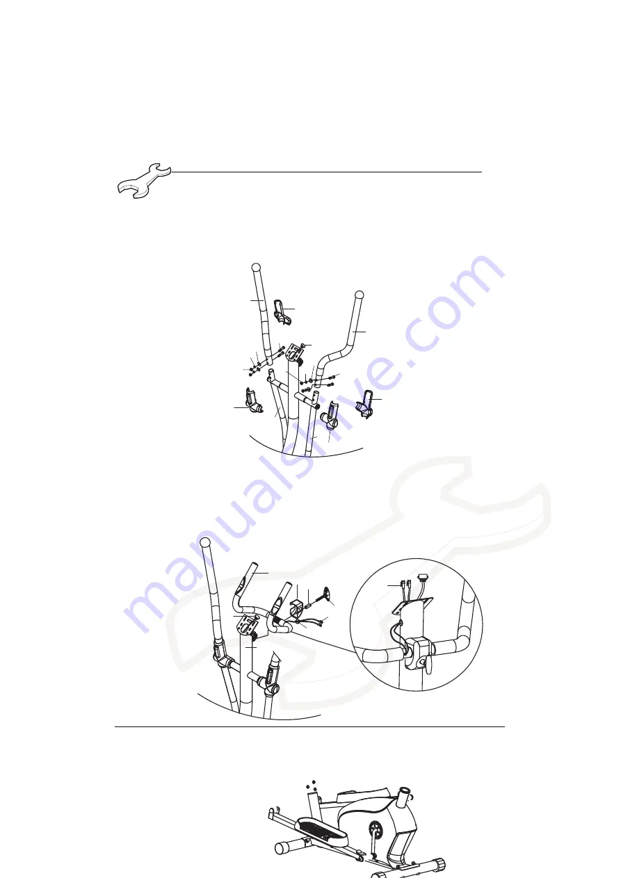
Fit the correctly labelled (L or R) Dual Action Handlebar - Upper (3/4) into the
appropriate Dual Action Handlebar - Lower (5L/R) and secure in place using
4 x M8 x 40mm Hex Bolts (47) (from the front), 4 x M8 Flat Washers (20), 
4 x M8 Spring Washers (23) and 4 x M8 Locking Nuts (42) for each side as 
shown below. Assemble the Front Handlebar Covers (32 & 43) to the Rear 
Handlebar Covers (31 & 34) over the Dual Handlebars as shown.

6

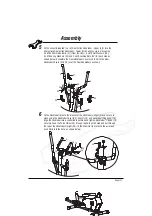
Fit the Handlebar (9) onto the bracket of the Handlebar Upright (2) and secure in 
place using the Handlebar Cover (48), Spacer (19) and Handlebar Wing Knob (18). 
Align the handlebar into a comfortable position and tighten Handlebar "T" Knob (18) 
securely. Feed the Pulse Wires (45) through the hole on the side and out through 
the top of the Handlebar Upright (20), fit the Grommet (44) around the wires and 
push firmly into the hole, as shown below.

4

5L

9

48 19

18

45

44

45

29

2

5R

29

20

23

42

47

20

23

42

32

47

34

43

3

31

Page 1

Summary of Contents for PMCE-1

Page 1: ...mbly User Manual use your new product and retain for future use Please ensure that you read this manual carefully before attempting to assemble or PMCE 1 Programmable Magnetic i l l E c e l y C 1 n i 2 ptical Trainer ...

Page 2: ......

Page 3: ...ction Page General Information 4 Before You Start 5 Safety 6 Exercise Information 7 Assembly 13 Page 3 Protect the environment by not disposing of this product with household waste Monitor Operation Instruction 21 ...

Page 4: ...eturned to our warehouse at the purchaser s cost c Replace the product if it is deemed by us to be economical to do so This guarantee does not cover wear and tear on upholstery or consumables This guarantee does not cover abuse defects caused by storage or use outside those intended If you need to advise us of a defect with your product and in order for us to service any requirement for replacemen...

Page 5: ...he components may be large heavy or awkward to handle alone Open the Carton Carefully open the carton that contains your product taking note of the warnings printed on the carton to ensure that the risk of injury is reduced Be aware of sharp staples that may be used to fasten the flaps as these may cause injury Be sure to open the carton the right way up as this will be the easiest and safest way ...

Page 6: ...r mental and physical development and above all their temperament should be taken into account They should be controlled and instructed to the correct use of the equipment The equipment is under no circum stances suitable as a children s toy For your own safety always ensure that there is at least 2 metres of free space in all directions around your product while you are exercising Regularly check...

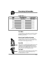
Page 7: ...our heart With regular exercise your cardiovascular system will become stronger and more efficient Your recovery rate i e the time taken for your heart to reach its normal resting level will also decrease Initially you may only be able to exercise for a few minutes each day Do not hesitate to breathe through your mouth should you need more oxygen Use the talk test If you cannot carry on a conversa...

Page 8: ...ur heart is working in its exercise target zone you need to be able to take your pulse If you do not have a pulse monitor either from the product you are using or a proprietary independent unit you will need to locate the pulse in your carotid artery This is situated in the side of the neck and can be felt by using the index and middle fingers Simply count the number of beats you feel in 10 second...

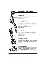
Page 9: ...Exercises Hold each stretch for a minimum of ten seconds and then relax Repeat each stretch two or three times Do this before your Aerobic Exercise session and also after you have finished Head Roll Rotate your head to the right for one count feeling a slight pull on the left side of your neck Next rotate your head back for one count stretching your chin Then rotate your head to the left for one c...

Page 10: ...ch Open both arms to the side and gently lift them above your head Reach your right arm as high as you can for one count gently stretching the muscles of the stomach and lower back Repeat the action with your left arm Repeat 3 4 times Inner Thigh Stretch Sit on the floor and pull your legs toward your groin the soles of your feet together Hold your back straight and lean forward over your feet Tig...

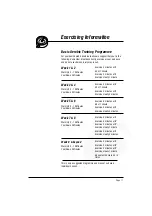
Page 11: ...10 Minutes Cool Down 5 Minutes Exercise 4 minutes at A Rest 1 minute Exercise 2 minutes at A Exercise slowly 1 minute Exercise 5 minutes at A Rest 1 minute Exercise 3 minutes at A Exercise slowly 2 minutes Exercise 6 minutes at A Rest 1 minute Exercise 4 minutes at A Exercise slowly 3 minutes Exercise 5 minutes at A Exercise 3 minutes at B Exercise 2 minutes at A Exercise slowly 1 minute Exercise ...

Page 12: ... plastic components a general household cleaner can be used but please be sure to dry the trainer and any attachments before use In the interest of safety do NOT use polish or any lubricant on the foam handgrips footplates Note 75 Mains Power Supply Your Programmable Magnetic Elliptical Trainer is powered by the 8VDC 500mA Mains Adapter included Please ensure that the Power Lead is correctly inser...

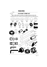
Page 13: ... 2 Item 27 Qty 4 Item 46 Qty 2 Item 23 Qty 14 Item 35L Qty 1 Item 18 Qty 1 Item 35R Qty 1 Item 20 Qty 9 Item 38L R Qty 2 Item 42 Qty 4 Item 26 Qty 2 Item 36 Qty 2 Item 37 Qty 2 Item 41 Qty 4 Item 28 Qty 8 Item 25 Qty 2 Item 17 Qty 4 Item 33 Qty 4 Item 40 Qty 4 Item 48 Qty 1 Item 16 Qty 1 Item 15 Qty 1 Item D Qty 1 Item C Qty 1 Item B Qty 1 Item A Qty 1 Item 47 Qty 4 Item 19 Qty 1 Item 39 Qty 2 Ite...

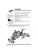
Page 14: ...nt please do not return the product to your retailer before contacting us first Tel 01535 637711 or Fax 01535 637722 or E mail support benysports co uk CUSTOMER SUPPORT is open from 9 00am to 5 00pm from Monday to Friday Do NOT FULLY TIGHTEN any Bolts Nuts or Fittings at this stage unless specifically instructed to do so Note Assemble the Front and Rear Stabilisers 6 12 to the Main Frame 7 using 4...

Page 15: ...olts 27 4 x M8 Spring Washers 23 and 4 x M8 Curved Washers 28 Do not fully tighten at this stage 3 Attach both Footplates 14L R to the Footplate Support Bars 8L R using 4 x M8 x 50mm Hex Bolts 33 4 x M8 Flat Washers 20 and 4 x M8 Locking Knobs 17 for each Footplate Align both Footplates in either of the 3 positions and tighten the Locking Knobs 17 securely 30 29 29 2 14L 14R 33 33 20 8L 8R 17 20 1...

Page 16: ...rough the Footplate Support Bar Pivot Bracket 58 and into the Crank Arms then fit 1 x M13 Spring Washer 36 and 1 x M13 Nylon Locknut 38L R for each side to secure the complete assembly Cap the M13 Nylon Locknut with 1 x S18 Round Cap 39 for each side SEE NOTE ii Fit the 2 x Handlebar Spacers 46 and 2 x M20 Wave Washers 26 one each side of the Handlebar Upright Pivot Bar as shown below Now fit the ...

Page 17: ...dlebar Covers 31 34 over the Dual Handlebars as shown 6 Fit the Handlebar 9 onto the bracket of the Handlebar Upright 2 and secure in place using the Handlebar Cover 48 Spacer 19 and Handlebar Wing Knob 18 Align the handlebar into a comfortable position and tighten Handlebar T Knob 18 securely Feed the Pulse Wires 45 through the hole on the side and out through the top of the Handlebar Upright 20 ...

Page 18: ...ddle Stem Support 10 to the Saddle Post 11 using 1 x M8 Flat Washer 20 and 1 x Saddle Adjustment Knob 16 Unscrew the Saddle Height Adjustment Knob 15 from Main Frame 7 then insert the Saddle Post 11 to the Main Frame 7 Adjust the Saddle to the desired height allowing for a slight knee bend at the bottom of the pedal action Tighten the Saddle Height Adjustment Knob 15 after adjustment Note Set the ...

Page 19: ...Assembly Page ...
Page 20: ...3 Nylon Locknut L S18 Round Cap M8 x 75mm Carriage Bolt M8 Dome Nut 44 46 Grommet 45 Handlebar Spacer Saddle Pulse Wire 29 30 31 32 33 34 35L 35R 36 37 38L 1 M13 Nylon Locknut R 38R 39 40 41 9 1 M8 Lock Nut Front Handlebar Cover Right 42 43 28 27 26 25 24 23 22 21 20 19 18 17 16 15 14L R 13 12 11 10 9 8L R 7 6 5L R 4 3 2 1 M8 x 40mm Hex Bolt Handlebar Cover M10 x 45mm Hex Bolt 49 48 47 2 M4 x 20mm...

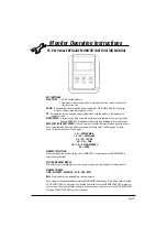
Page 21: ...when the monitor has a heart rate value Recovery Values are shown as Fitness Level 1 6 after approx 1 minute Level 1 is the best and Level 6 is the worst WORKOUT SELECTION After powering up the monitor use the UP or DOWN KEYS to select then press MODE ENTER to enter the desired modes SETTING WORKOUT MODES After selecting your desired program you may pre set several workout modes for desired result...

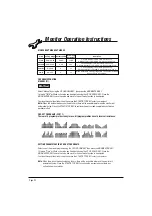
Page 22: ...R DOWN KEY Press the MODE ENTER KEY to save the value and move to the next mode function to be adjusted Note When the workout modes count down to zero there will be an audible alarm and the monitor will automatically stop Press the START STOP KEY to continue the workout and complete any unfinished workout modes PRE SET PROGRAMS P2 P11 There are 10 program profiles ready for use All program profile...

Page 23: ...adjusted Continue through all desired modes then press the START STOP KEY to start your workout Note If your Pulse is above or below the set TARGET H R the monitor will adjust the resistance load automatically The monitor will re check approx every 25 seconds and the resistance load will increase or decrease as required Note When the workout modes count down to zero there will be an audible alarm ...

Page 24: ...is open from 9 00am to 5 00pm from Monday to Friday Tel 01535 637711 E mail support benysports co uk Fax 01535 637722 Unit 8 Riparian Way The Crossings Cross Hills West Yorkshire BD20 7BW Website www benysports co uk Copyright BSCL May 2018 ...

Reviews: