background image

Summary of Contents for iMars XG100KTR

Page 1: ...Operation Manual Photovoltaic Grid connected Inverter iiiiiiim 5 ffl...

Page 2: ...ons seriously before any moving installation operation and maintenance to ensure correct use and high performance of operation on the inverter The use of the iMars series grid tied solar inverters mus...

Page 3: ...ure 2 2 Appearance of inverter 5 5 6 2 3 Nameplate 8 2 4 Product model 9 2 5 Outline dimension and weight 9 2 6 The LED light panel 2 6 1 The modern model of the LED panel 2 6 2 Classic LED light pane...

Page 4: ...erminal block grid connection 5 4 2 Parallel connection requirements of multiple inverters 23 24 26 26 27 5 5 Connect the communication line 28 5 5 1 Interface description 28 6 Running 6 1Inspection b...

Page 5: ...cribes various warning symbols in operation manual and provides safety instructions for the installation operation maintenance and use of the iMars series grid tied solar inverters 1 1 Warning marks W...

Page 6: ...Do not refit the inverter unless authorized A All the electrical installation must conform to local and national electrical standards A Do not touch the housing of the inverter or the radiator to avo...

Page 7: ...ombustible objects keep the inverter away from flammable and combustible objects Do not install the inverter in places easily accessible to children or other public Remove the metal accessories in han...

Page 8: ...disconnect the breaker on grid side then disconnect the breaker connected to the PV component and wait for at least 5 minutes until the internal parts of the inverter are fully discharged The internal...

Page 9: ...Application of PV grid connected inverter The PV grid connected inverter is the core part of solar PV grid connected power generation system The sunlight can be converted to DC energy through PV compo...

Page 10: ...3 N PEN N PE PE v PE PE PE Solar Inverter Solar Inverter Solar Inverter TT IT Transformer Transformer L1 L1 s L2 L2 L3 L3 N v r i PE Solar Inverter Solar Inverter Fig 2 2 Type of grid 2 2 Appearance o...

Page 11: ...array 2 Communication interface RS485 communication interface and its extension port EXT 3 AC terminal Inverter AC output port connect to public grid 4 5 LED light Instructions inverter current worki...

Page 12: ...rent 158 8A 2 Rated Power 100000W Max Apparent Power lioooow Frequency 50Hz 60Hz Power factor range 0 80un 0 80ov Environment Temperature 30 C 60 C I Protective Class Inverter topology Non isolated In...

Page 13: ...s of three phase PV grid connected inverter Product name Model Rated output power W three phase L1 L2 L3 N PE three phase photovoltaic grid connected inverter XG100KTR 100 three phase photovoltaic gri...

Page 14: ...weight kg Model 100kW 660 1050 330 95 110kW 660 1050 330 98 136kW 660 1050 330 101 Fig 2 6 Dimension of paper package Table 2 4 Package dimension and gross weight Height mm Width Depth mm Weight Packa...

Page 15: ...cator light state description Normal grid connected power generation Blue light is ON Dc or ac has electricity inverter was in a state of standby or start Not Grid connected Blue light flashing period...

Page 16: ...ected normally and the DC input voltage of the corresponding MPPT circuit is greater than or equal to 200V Green light is ON PV connection indicator The inverter is disconnected from all PV Green ligh...

Page 17: ...ng indicator Alarm Red light flashingquickly 0 5s ON 0 5s OFF status The inverter has a secondary alarm Red light is ON The inverter has an important alarm 2 7 Bottom of chassis XG100 110KTR is equipp...

Page 18: ...at 5 RH 95 RH The stacking of inverters is recommended to be placed according to the number of stacking layers in the original shipment Place the inverter carefully during stacking to avoid personal i...

Page 19: ...e box and whether the product package is intact If any damage is detected please contact the shipping company or the supplier directly Please also provide photos of the damage to get our fastest and b...

Page 20: ...4 2 List of installation tool No Installation tool Purpose 1 Marker Indicate the installation hole 2 Electric drill Drill holes in the bracket or on the wall 3 Hammer Knock on the expansion bolt 4 Adj...

Page 21: ...ed in a well ventilated environment to ensure good heat dissipation 5 It is recommended to choose the installation site with shelter or build sunshade 0KWG Pfk I Fig 4 2 sunshade 6 The installation en...

Page 22: ...t area 2 There is enough reserved space around the installation site to facilitate the disassembly and assembly of inverter and air convection As shown in Figure 4 3 i 600mm hut 7 800mm X J 300mm c 0...

Page 23: ...horizontal line as shown in Figure 4 5 Please install the inverter vertically or backward 15 to facilitate the heat dissipation of the machine Do not tilt the inverter forward horizontally upside down...

Page 24: ...mark it with a marking pen Q n SB sngr L L e L tr 0 fa Step 2 Drillholes on the wall with electric drill Step 3 Align the hanging plate with the hole position and put the combination bolt flat pad sp...

Page 25: ...rs need to prepare expansion bolts by themseles and it is recommended to use M10 95 stainless steel pressure explosion expansion bolt I i r L L 1 T i L n L J 1 1 _L 1 r I 1 1 L 1 L L T T Step 3 Fix th...

Page 26: ...then pause and check the fastening of the lifting ring and rope After confirming that the connection is firm lift the inverter to the destination Step 3 lnsert the hooks on the left and right sides of...

Page 27: ...ries or even death during system operation All the electrical installation must conform to the national and regulations concerning electrical safety regulations Ensure all the cables are installed fir...

Page 28: ...ules to the DC connector as fig 5 2 shows Loose the nut of connector and remove the isolation layer of the DC cable for about 15mm Insert it into the connector and press until heart the lock sound Fin...

Page 29: ...nverter do not use other connection devices without authorization from our company otherwise damage to the device unstable operation or fire may occur and our company will not undertake quality assura...

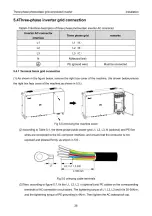
Page 30: ...the right box face cover of the machine as shown in 5 5 ii x V Fig 5 5 removing the machine cover 2 According to Table 5 1 the three phase public power grid L1 L2 L3 N optional and PE five wires are...

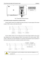
Page 31: ...r 1 Inverter 2 Connect multiple inverters to the low voltage side of the medium voltage transformer and connect high voltage side to the medium voltage grid directly If total capacity of the inverter...

Page 32: ...onnect the communication line 5 5 1 Interface description The position of inverter communication terminal block in the chassis and its equipped terminals are shown in the figure below r n I BBS T invi...

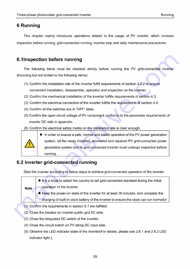
Page 33: ...rements of inverter DC side in appendix 6 Confirm the electrical safety marks on the installation site is clear enough In order to ensure a safe normal and stable operation of the PV power generation...

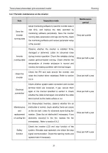
Page 34: ...input side 4 Wait for at least 5 minutes until the internal parts of the inverter are fully discharged and complete the stop operation 6 4Daily maintenance and inspection In solar PV grid connected p...

Page 35: ...Check the RH and dust around the inverter and clean the inverter when necessary Refer to section 6 4 2 Clean the Once per half a year inverter Check whether system cable connection and inverter termin...

Page 36: ...disconnect all the power inputs of the inverter Before carrying out maintenance operation wait for at least 10 minutes until the internal capacitors of the inverter are fully discharged The fan can be...

Page 37: ...damaged remove the damaged fan and install a good fan to the original position Step 7 Install the fan tray back to the inverter in reverse order and restart the inverter Once the inverter stops due t...

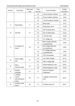
Page 38: ...03 03 03 01 Inverter hardware flow 05 01 02 Inverter software flow 05 02 3 Flow failures 05 The BOOST hardware 03 05 03 flow 04 The BOOST software flow 05 04 The inverter temperature thermal 01 06 01...

Page 39: ...fault 14 03 AC voltage test 19 01 01 BUS voltage detecting inconsistencies 02 19 02 Consistency of failure ISO voltage detecting inconsistencies 11 19 03 19 03 PV voltage detecting inconsistencies 04...

Page 40: ...06 07 Fan7 01 07 08 Fan8 01 08 09 Fan9 01 09 10 Fan10 01 10 Lightning protector 2 02 01 Lightning protector 02 01 01 String 1 03 01 02 String2 03 02 03 String3 03 03 04 String4 03 04 05 String5 03 05...

Page 41: ...nverter Fault isolation If any problem please contact with the supplier and provide following information Model of the inverter Serial No of the inverter System version version 1 version 2 MCU softwar...

Page 42: ...ted voltage and frequency range V AC 158 8 174 6 174 6 160 4 MaxAC output current A 0 8 0 8 adjustable Power factor 3 at rated power Harmonic wave distortion Intelligent air cooling Cooling mode 98 70...

Reviews: