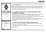
• Unscrew the screw on the down rod’s hanger ball, then
loosen the hanger ball. Remove the stop pin from inside the
down rod and remove the hanger ball from the rod.
• Remove the clevis pin and hairpin clip from the down rod. If
you prefer using the longer down rod, install the hanger ball on
it and make sure to move the earth wire from one to the other.
Pass the electrical supply leads from the top of the motor all
the way through the down rod until they come out the other
end.
• Insert the down rod into the motor housing’s hole and turn it
in order to align the holes on both sides with the holes on the
down rod.
• Pass the clevis pin through the holes so that it passes through
the down rod too, be careful not to damage any of the wires.
Pass the hairpin clip through the clevis pin so that it is securely
fixed.
• Tighten all the screws set up to the moment. This will ensure
minimum rod and fan tumbling.
2.2. INSTALLATION OF THE DOWN ROD AND HANGER BALL
ENGLISH
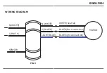
FIG 4
FIG 5
Summary of Contents for VT-6052-5
Page 33: ...8 8 8 2 3 m 45 kg 8 3 mm BULGARIAN...
Page 34: ...150 mm 6 BULGARIAN...
Page 35: ...BG V TAC 2 10 12 24 BULGARIAN...
Page 36: ...1 1 2 3 4 5 6 7 8 1 2 2 1 3 3 2 9 10 11 12 13 14 15 BULGARIAN...
Page 37: ...2 2 4 U 4 5 U U 5 5 6 6 2 3 7 7 7 2 4 8 9 BULGARIAN...
Page 38: ...2 5 3 10 3 10 10 2 6 LED 11 3 12 H M L BULGARIAN...
Page 39: ...1H 1 2H 2 4H 4 8H 8 1 2 1 A23 12V 3 4 1 2 BULGARIAN...
Page 40: ...5 1 2 1 2 3 4 5 6 7 1 2 3 1 2 BULGARIAN...
Page 81: ...8 8 8 2 3 45 kg 8 GREEK...
Page 82: ...3 mm 150 mm 6 GREEK...
Page 83: ...EL V TAC V TAC 2 10 12 24 GREEK...
Page 84: ...1 1 2 3 4 5 6 7 8 1 2 2 1 3 3 2 9 10 11 12 13 14 15 GREEK...
Page 85: ...2 2 4 U 4 5 U U 5 5 6 6 2 3 2 4 8 9 2 5 3 10 GREEK...
Page 86: ...3 10 10 2 6 LED 11 3 12 H M L 1H 1 2H 2 4H 4 8H 8 GREEK...
Page 87: ...1 2 A23 12V 3 4 1 2 GREEK...


