• If screws are not properly tightened, the motor might oscillate. This
could be dangerous.
• Once the above steps are all finished, install the hanger ball onto the
down rod, insert the stop pin in the down rod and lift up the hanger
ball. Then, tighten all the screws firmly so that all the elements are
completely and securely fixed.
2.3. HANGING THE FAN TO THE MOUNTING BRACKET AND
ATTACHING THE BLADES
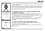
• Lift the fan up to the mounting bracket, insert the hanger ball in the
mounting bracket through the opening and carefully let it rest.
• Rotate the ball and make sure that the tab located in the mounting
bracket is aligned with the hanging ball’s slot.
• When aligned, the fan will automatically sit on its correct position.
This will prevent rotation of the rod and fan when the unit is
operating.
2.4. REMOTE CONTROL AND WIRING INSTRUCTION
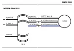
• Place the receiver through the hanging bracket and connect the
wires following the colour codes.
• Connect the push connectors from the fan to the remote control as
stated below:
ENGLISH
ENGLISH
FIG 6
FIG 7
FIG 8
Summary of Contents for VT-6052-5
Page 33: ...8 8 8 2 3 m 45 kg 8 3 mm BULGARIAN...
Page 34: ...150 mm 6 BULGARIAN...
Page 35: ...BG V TAC 2 10 12 24 BULGARIAN...
Page 36: ...1 1 2 3 4 5 6 7 8 1 2 2 1 3 3 2 9 10 11 12 13 14 15 BULGARIAN...
Page 37: ...2 2 4 U 4 5 U U 5 5 6 6 2 3 7 7 7 2 4 8 9 BULGARIAN...
Page 38: ...2 5 3 10 3 10 10 2 6 LED 11 3 12 H M L BULGARIAN...
Page 39: ...1H 1 2H 2 4H 4 8H 8 1 2 1 A23 12V 3 4 1 2 BULGARIAN...
Page 40: ...5 1 2 1 2 3 4 5 6 7 1 2 3 1 2 BULGARIAN...
Page 81: ...8 8 8 2 3 45 kg 8 GREEK...
Page 82: ...3 mm 150 mm 6 GREEK...
Page 83: ...EL V TAC V TAC 2 10 12 24 GREEK...
Page 84: ...1 1 2 3 4 5 6 7 8 1 2 2 1 3 3 2 9 10 11 12 13 14 15 GREEK...
Page 85: ...2 2 4 U 4 5 U U 5 5 6 6 2 3 2 4 8 9 2 5 3 10 GREEK...
Page 86: ...3 10 10 2 6 LED 11 3 12 H M L 1H 1 2H 2 4H 4 8H 8 GREEK...
Page 87: ...1 2 A23 12V 3 4 1 2 GREEK...


