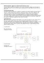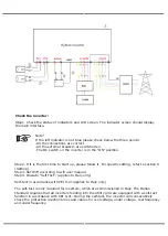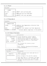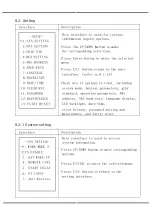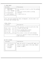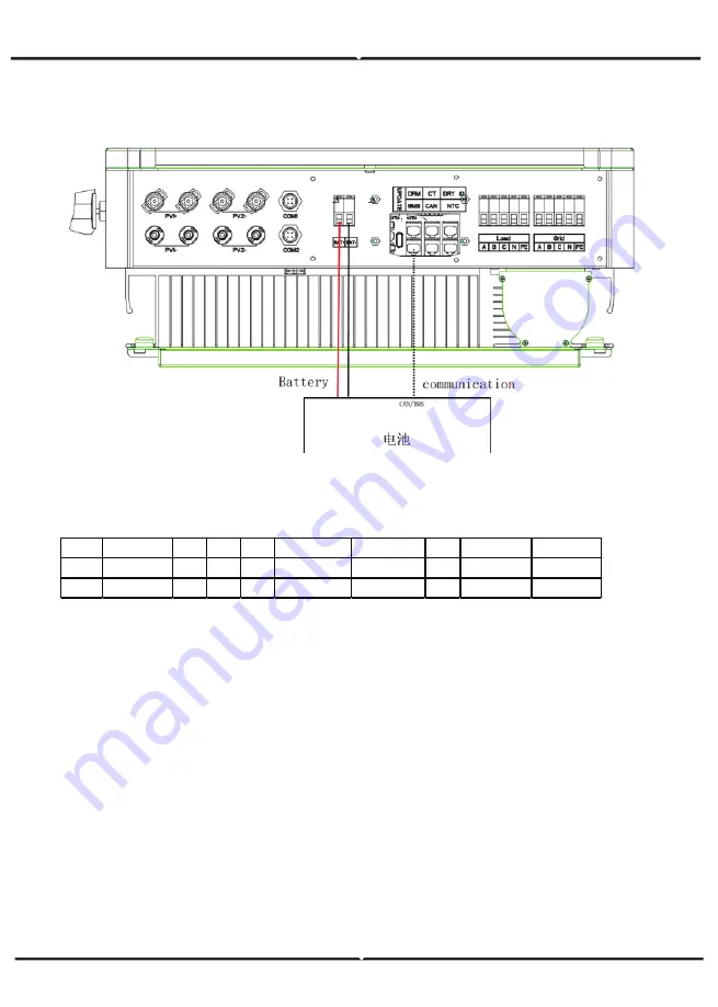
BATTERY CONNECTION DIAGRAM
BMS PIN DEFINITION
Communication interface bewteen inverter and battery is RS485 or CAN with a RJ45 connector.
When using RS485 protocol, please note that PIN2 must be disconnected.
Note
!
The battery communication can only work when the battery BMS is compatible with the
inverter.
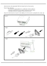
POWER CONNECTION STEPS:
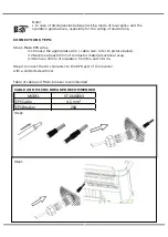
Step1. Choose the 2 AWG wire and strip the cable to 15mm.
Step2. Select two O-terminals with an aperture of M6.
Step3. Insert the stripping line into the O-terminal and clamp it with a crimping clamp.
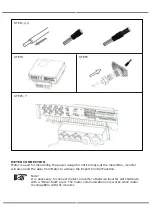
Step4. Remove waterproof cover plate.
Step5. Disassemble the waterproof connector and pass the cable through the waterproof
connector.
Step6. Connect the cable to the terminal of the inverter.
Step7. Assemble waterproof connectors and waterproof covers plate.
PIN
1
2
3
4
5
6
7
8
CAN
Definition
X
X
X
BMS_CANH BMS_CANL
X
X
X
Rs485
Definition
X
X
X
X
X
GND BMS_485A BMS_485B
Summary of Contents for VT-6608303
Page 33: ...8 1 7 Grid connected output 8 1 8 Inverter output 8 1 9 Load 8 1 10 Power...
Page 34: ...8 1 11 Power 8 1 12 Temperature 8 1 13 Status information 8 1 14 Error information...
Page 36: ...8 2 Setting 8 2 1 System setting...
Page 37: ......
Page 38: ......
Page 39: ...8 2 2 BAT Setting...
Page 40: ......
Page 41: ...8 2 3 Grid standard...
Page 42: ...8 2 4 System setting...
Page 43: ......
Page 44: ......
Page 45: ...8 2 5 485 Address 8 2 6 485 Baud rate 8 2 7 Language...
Page 46: ...8 2 8 LCD backlight 8 2 9 Date time 8 2 10 Clear history...
Page 47: ...8 2 11 Password Setting 8 2 12 Maintenance 8 2 13 Factory reset 8 2 14 Inquiry...
Page 48: ......
Page 49: ...8 2 12 Statistics...
Page 50: ......
Page 52: ......
Page 53: ......
Page 54: ......

