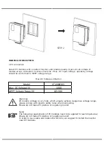
• Prior to the application, please read this section carefully to ensure correct and safe
application. Please keep the user manual properly.
• Accesories only together with the inverter shipment are recommended here. Otherwise
may result in a risk of fire, electric shock, or injury to person.
•
Make sure that existing wiring is in good condition and that wire is not undersized.
• Do not disassemble any parts of inverter which are not mentioned in installation guide.
It contains no user-serviceable parts. See Warranty for instructions on obtaining service.
Attempting to service the inverter yourself may result in a risk of electric shock or fire
and will void your warranty.
• Keep away from flammable, explosive materials to avoid fire disaster. The installation
place should be away from humid or corrosive substance.
• Authorized service personnel must use insulated tools when installing or working with
this equipment.
• PV modules shall have an IEC 61730 class A rating.
•
Never touch either the positive or negative pole of PV connecting device.
• Strictly prohibit touching both of them at the same time.
• The unit contains capacitors that remain charged to a potentially lethal voltage after the
MAINS , battery and PV supply has been disconnected.
• Hazardous voltage will present for up to 5 minutes after disconnection from power
supply.
•
CAUTION-RISK of electric shock from energy stored in capacitor, Never operate on the
inverter couplers, the MAINS cables, Battery cables, PV cables or the PV generator when
power is applied. After switching o ffthe PV , battery and Mains, always wait for 5minutes
to let the intermediate circuit capacitors discharge before unpluging DC ,battery inplug
and MAINS couplers.
• When accessing the internal circuit of inverter, it is very important to wait 5 minutes
before operating the power circuit or demounting the electrolyte capacitors inside the
device. Do not open the device before hand since the capacitors require time sufficiently
discharge!
•
Measure the voltage between terminals UDC+ and UDC- with a multi-meter(impedance
at least 1Mohm) to ensure that the device is discharged before beginning work (35VDC)
inside the device.
Surge protection devices (SPDs) for PV installation
• Lightning will cause a damage either from a direct strike or from surges due to a nearby
strike.
• Induced surges are the most likely cause of lightning damage in majority or installa-
tions, especially in rural areas where electricity is usually provided by long overhead lines.
Surge may be included on both the PV array conduction and the AC cables leading to the
building.
• Specialists in lightning protection should be consulted during the end use application.
Using appropriate external lightning protection, the effect of a direct lightning strike into
a building can be mitigated in a controlled way, and the lightning current can be
discharged into the ground.
• Installation of SPDs to protect the inverter against mechanical damage and excessive
stress include a surge arrester in case of a building with external lightning protection
system (LPS) when separation distance is kept.
•
To protect the DC system, surge suppression device (SPD type2) should be fitted at the
inverter end of the DC cabling and at the array located between the inverter and the PV
generator, if the voltage protection level (VP) of the surge arresters is greater than
1100V, an additional SPD type 3 required for surge protection for electrical devices.
•
To protect the AC system, surge suppression devices (SPD type2) should be fitted at the
main incoming point of AC supply (at the consumer's cutout),located between the
inverter and the meter/distribution system; SPD (test impulse D1) for signal ine accord
-
ing l to EN 61632-1.
• All DC cables should be installed to provide as short a run as possible, and positive and
negative cables of the string or main DC supply should be bundled together.
DIMENSION
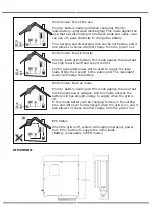
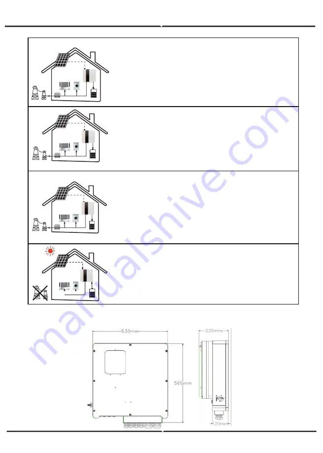
Work modes: Force time use
Priority: battery>load>grid(when charging) Priority:
load>battery>grid(when discharging) This mode applies the
area that has electricity price between peak and valley. User
can use off- peak electricity to charge the battery.
The charging and discharging time can be set flexibly, and it
also allows to choose whether charge from the grid or not.
Work modes: Feed in Priority
Priority: load>grid>battery This mode applies the area that
has high feed-in tariff and export control.
The PV generated power will be used to supply the local
loads firstly, then export to the public grid. The redundant
power will charge the battery.
Work modes: Back up mode
Priority: battery>load>grid This mode applies the area that
has frequent power outages. And this mode ensures the
battery will has enough energy to supply when the grid is
off.
In this mode battery will be charging forcibly in the setting
time and will never be discharged when the grid is on, and it
also allows to choose whether charge from the grid or not.
EPS Status
When the grid is off, system will supply emergency power
from PV or battery to supply the home loads.
(Battery is necessary in EPS mode.)
Summary of Contents for VT-6608303
Page 33: ...8 1 7 Grid connected output 8 1 8 Inverter output 8 1 9 Load 8 1 10 Power...
Page 34: ...8 1 11 Power 8 1 12 Temperature 8 1 13 Status information 8 1 14 Error information...
Page 36: ...8 2 Setting 8 2 1 System setting...
Page 37: ......
Page 38: ......
Page 39: ...8 2 2 BAT Setting...
Page 40: ......
Page 41: ...8 2 3 Grid standard...
Page 42: ...8 2 4 System setting...
Page 43: ......
Page 44: ......
Page 45: ...8 2 5 485 Address 8 2 6 485 Baud rate 8 2 7 Language...
Page 46: ...8 2 8 LCD backlight 8 2 9 Date time 8 2 10 Clear history...
Page 47: ...8 2 11 Password Setting 8 2 12 Maintenance 8 2 13 Factory reset 8 2 14 Inquiry...
Page 48: ......
Page 49: ...8 2 12 Statistics...
Page 50: ......
Page 52: ......
Page 53: ......
Page 54: ......


