background image

-11-

 Basic IN-OUT  Wiring in Standard Mode

Connecting Multi Monitors

WIRING

• 

The door station is also compatible with 
other monitors which are provided by our 
company.

• 

Please set door station into group calling 
mode if there is more than 4 monitors in 
villa(Refer to Page 8)

• 

Distributor is unnecessary in full audio 
system, and IN-OUT mode is recom-
mended.

• 

For the last monitor connected to the 
system, DIP6 should set to 

ON

ID=0

Code=1, DIP6=off

Optional functional module

SCU

 camera module(max.4)

GSM

 module(mobile phone transfer)

TPS

 module(PBX transfer)

QSW

 image quad splitter module

(Master)

Code=1, DIP6=off

(Slave 2)

Code=1, DIP6=on

(Slave 3)

BUS(IM) BUS(DS)

PC6A

AC~

100~240VAC

Code=1, DIP6=off

(Slave 1)

SCU

GSM

TPS

QSW

Summary of Contents for DT607C Series

Page 1: ...AL DT ENG DT607C V1 201705 Please read this manual carefully to ensure safe and correct operation Keep this manual well for future reference DT607C S1 DT607C S2 DT607C S3 DT607C S4 DT607C Series 2 WIR...

Page 2: ......

Page 3: ...tation Calling Mode 4 Setting Unlock Mode 6 Setting Unlock Time 6 Setting Nameplate Illumination Mode 7 Setting Night View LED Illumination Mode 7 Setting Ring back Tone 8 WIRING 9 Connecting Electric...

Page 4: ...ny cover Rainy cover The distance between the top of main unit and rain cover should be not less than 3mm Main unit Main unit 3mm 1 Connect the cable correctly 2 Drill holes in the wall to match the s...

Page 5: ...g the door station to power the locks if using the external power supply for the locks the S will not be connected 1 2 3 Lock Control Jumper PIR Motion Detector Connect Port 12V GND PIR L1 L2 PL S S M...

Page 6: ...up of the LED indicator on the unit and by the sounding of the buzzer Order Setting items Setting range Default value 1 Setting door station address 0 3 0 2 Setting door station calling mode Standard...

Page 7: ...FF TALK Indicator OFF Buzzer Beep Beep UNLOCK Indicator OFF TALK Indicator OFF Buzzer Beep Beep Beep UNLOCK Indicator OFF TALK Indicator OFF Buzzer Beep Beep Beep Beep ID 0 1st door station ID 1 2nd d...

Page 8: ...the monitor with address 02 by default Call buttonC call the monitor with address 03 by default Call buttonD call the monitor with address 04 by default Call buttonA Call all monitors in group address...

Page 9: ...e until exit out the setting mode If without any operation in 10 seconds it will exit out setting mode automatically In this step press KEY_SET button twice to exit out the setting mode manually Setti...

Page 10: ...it will exit out setting mode automatically In this step press KEY_SET button twice to exit out the setting mode manually Setting Night View LED Illumination Mode There are 3 working modes for night v...

Page 11: ...eep Press KEY_1 button to set the ring back call tone ringing one time UNLOCK Indicator ON TALK Indicator ON Buzzer Beep Beep Press KEY_1 button again to set the ring back call tone ringing continuous...

Page 12: ...Exit Button EB 5 The Unlock Mode must be set to 0 by default 1 The external power supply must be used according to the lock 2 The inside relay contact is restricted to 230Vac 1A or 24Vdc 1A 3 The jum...

Page 13: ...S ID 0 Code 1 DIP6 on 1 2 3 4 5 6 ON DIP L2 L1 DIP Switches PC6A AC 100 240VAC 100 240VAC DBC4A1 A B C D OFF ON Impedance switch BUS IM BUS DS PC6A AC ID 0 1st door station ID 1 2nd door station ID 2...

Page 14: ...a Refer to Page 8 Distributor is unnecessary in full audio system and IN OUT mode is recom mended For the last monitor connected to the system DIP6 should set to ON ID 0 Code 1 DIP6 off Optional funct...

Page 15: ...a distributor for the extension WIRING DBC4A1 A B C D RLC DBC4A1 OFF ON Impedance switch BUS IM BUS DS Code 1 DIP6 on Code 2 DIP6 on Code 3 DIP6 on Code 4 DIP6 on ID 0 PC6A AC 100 240VAC Optional func...

Page 16: ...ptor which is supplied by the manufacture or approved by the manufacture Pay attention to the high voltage inside the products please refer service only to a trained and qualified professional APPENDI...

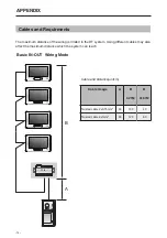
Page 17: ...is limited in the DT system Using different cables may also affect the maximum distance which the system can reach Cable and distance unit m Cable Usage A B 2 IM B 16 IM Twisted cable 2x0 75mm2 60 10...

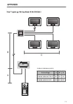
Page 18: ...15 B A C 2 2 DBC4A1 PC6A Cable and distance unit m Cable Usage A B C Twisted cable 2x0 75mm2 60 60 30 Twisted cable 2x1mm2 80 80 40 APPENDIX Star Topology Wiring Mode With DBC4A1...

Page 19: ...16 Note...

Page 20: ...The design and specifications can be changed without notice to the user Right to interpret and copyright of this manual are preserved DT ENG DT607C V1...

Reviews: