20
OEM TM-50 User’s Guide
The OEM TM-50 Controller
6174007.fm
Note
: When determining the leader/trailer
length, please note that the final length will
be
450 mm
plus the leader/trailer length
value that is entered in the controller set-
tings.
450 mm is the approximate distance from
the carrier tape cut point to the center of
the placement (or inspection point if the
vision option was purchased).
If a value is entered on this screen, the screen
in Figure 2.17 will appear.
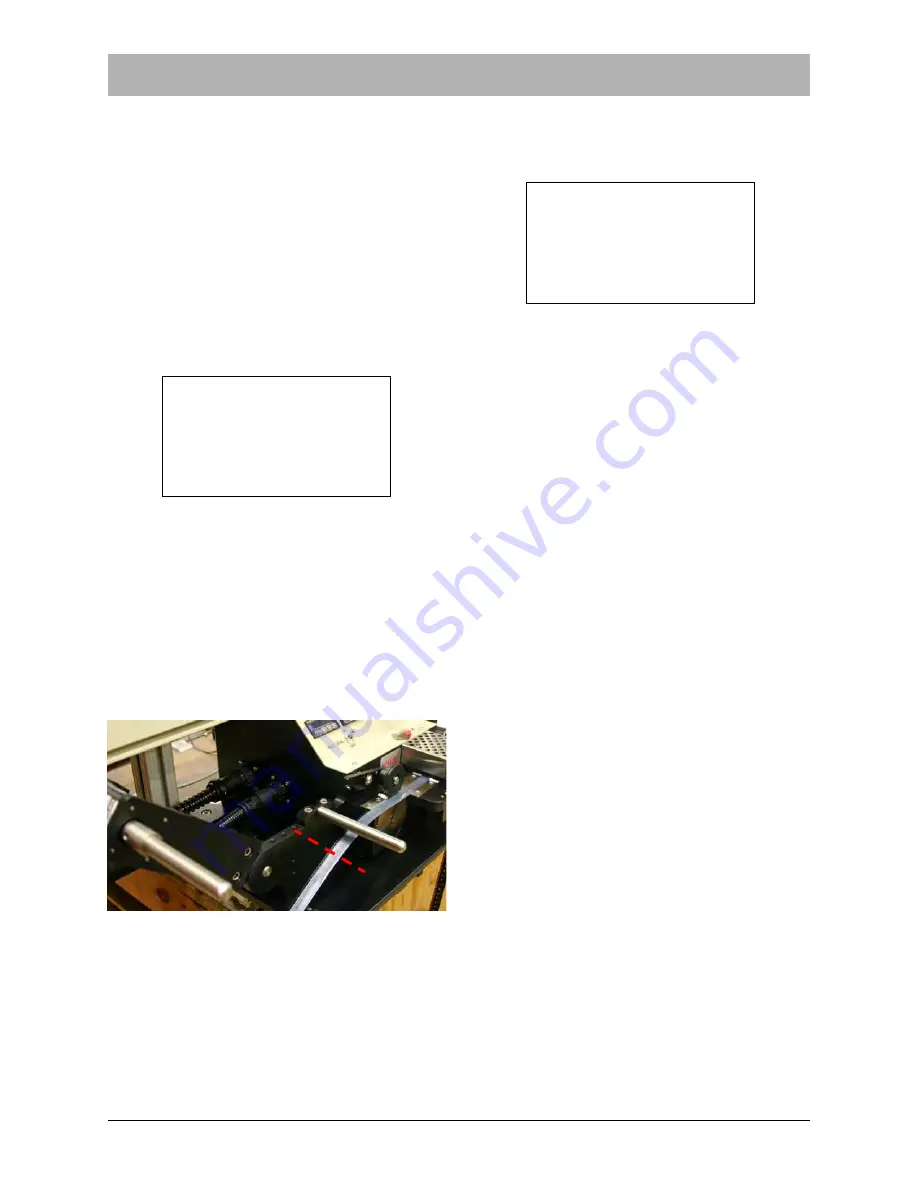
Figure 2.18 indicates a typical point of refer-
ence to use as a cut point. The machine does
not know at what point the operator will cut the
carrier tape, therefore, the software uses this
value to calculate how much total carrier
needs to be run out for the end of the previous
reel to reach the point the operator will cut it
off.
Determine the distance required in millimeters
and enter the value. The display will return to
the Mode Screen.
When the right arrow key is pressed in the
Integration screen, a second screen of options
will appear:
Tap Advance
When Tap Advance is enabled, the machine
will run continuously after the foot switch is
pressed and released and will not stop until
the foot switch is pressed, held down for a few
seconds and released again.
Power Recovery
When Power Recovery is enabled, the
machine will remember at what point in an
advance it had reached when power is cut. It
will then automatically complete that partial
advance when it is powered back up and
placed into Run Mode.
Manual/OEM Mode
The Manual/OEM option will toggle between
the two modes when the 3 key is pressed.
When the machine is in OEM mode, it will run
according to communication from a system it
has been integrated with. When it is in man-
ual mode, it will run manually with a foot
switch.
Press ESC until reaching the setup choice
screen, as shown in Figure 2.4.
ENTER TRAILER LENGTH
IN mm THEN PRESS
ENT.
NOW 200
Figure 2.17
Figure 2.18
Cut Point
1> TAP ADVANCE
2> POWER RECOVERY
3> MANUAL/OEM=OEM
Figure 2.19
Summary of Contents for OEM TM-50 SMD
Page 2: ......
Page 4: ......
Page 10: ...Safety Warning Labels 61685113 fm vi ...
Page 28: ...16 OEM TM 50 User s Guide Machine Overview 61685225 fm ...
Page 43: ...6174007 fm Using the Vision Port Chapter 2 Controller 29 Vision Hookup Example Figure 2 33 ...
Page 74: ...60 OEM TM 50 User s Guide Electrical Connections 6174322 fm Figure 4 6 ...
Page 95: ...61004015 fm Appendix A Sensors A 1 Appendix A Sensors ...
Page 102: ...Service and Parts Contacts 61053915 fm Page 2 ...
Page 104: ......
Page 106: ...TM 50 OEM Sensors Spare Parts List D219368 2 fm Page 1 of 1 ...
Page 108: ......
Page 110: ......
Page 111: ......


