ENGLISH
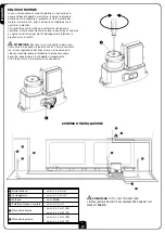
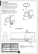
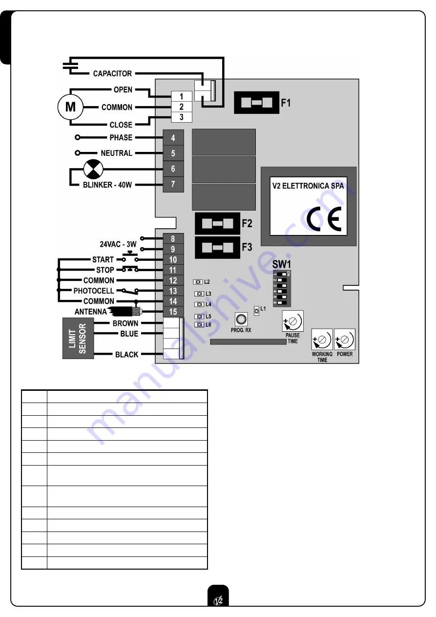
1.
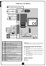
Motor power supply during the opening 230/120 VAC
2.
Motor common terminal
3.
Motor power supply during the closing
4.
Power supply phase wire 230/120 VAC
5.
Power supply neutral wire 230/120 VAC
6. - 7.
Blinker 230/120 VAC - 40 W
8. - 9.
Power supply output 24 VAC / 3 W for photocells and
other attachments
10.
Opening command for connections to: button panel,
key selector. Normally open contact
11.
STOP command. Normally closed contact
12.
Common (-)
13.
Photocell. Normally closed contact
14.
Antenna cable shielding
15.
Antenna
m
CAUTION:
Unused inputs that are normally closed (STOP
and PHOTOCELL) should be connected to the common wire (-).
STATUS INDICATORS OF THE UNIT INPUTS
L1
Programming
L2
Lights up when a pulse is received at the START input
terminal
L3
Goes out when a pulse is received at the STOP input terminal
L4
Goes out when a pulse is received at the PHOTOCELL
input terminal
L5
Goes out when a pulse is received at the opening limit
switch input terminal
L6
Goes out when a pulse is received at the closing limit
switch input terminal.
PROTECTION FUSES
F1
= 5 A
F2
= 160 mA
F3
= 250 mA
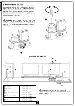
CONNECTIONS TO THE TERMINALS
12
Summary of Contents for Eco Gold
Page 33: ......

