


E
N
G
L
IS
H
37
CONTROL UNIT INSTALLATION
The installation of the control unit, the safety devices and the
accessories must be carried out with the power supply shut off.
POWER SUPPLY
The control unit must be supplied by an electrical line at
230V-50Hz (120V - 50/60Hz for the 120V models), protected
with a differential magnetothermic switch in compliance with the
law norms.
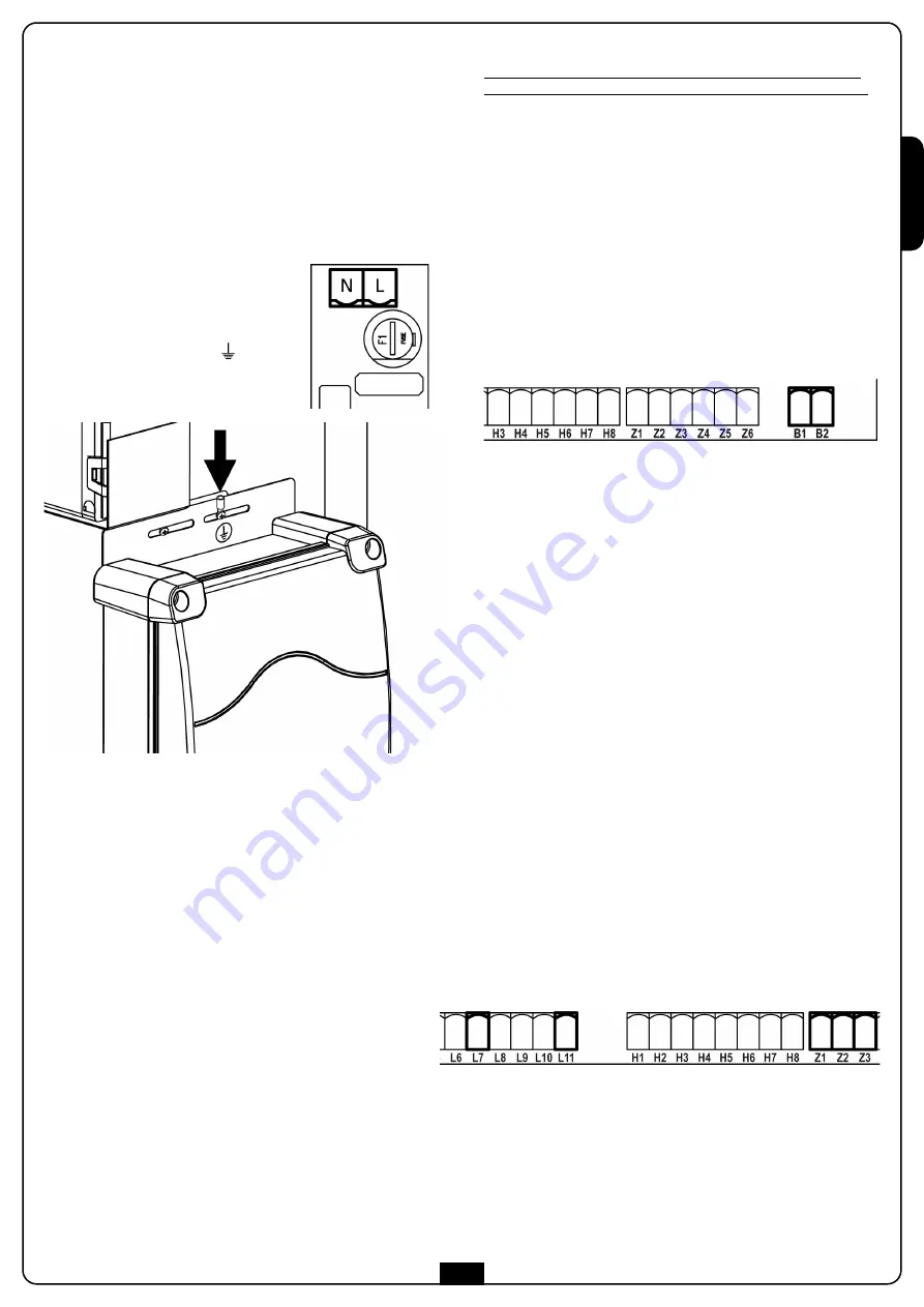
Connect the feeder cables to terminals
L
and
N
on the card positioned next to the
transformer.
Ground the motor to the terminal labeled
with the corresponding sign
using
the eyelet provided for the terminal.
ENERGY SAVING FUNCTION
This function is useful for reducing the energy consumption of
the automation device while in stand-by mode.
If the function is enabled, the control unit will enter ENERGY
SAVING mode under the following conditions:
• 30 seconds after completion of an operational cycle
• 30 seconds after an opening (if automatic closure is not
enabled)
• 30 seconds after exiting the programming menu
In ENERGY SAVING mode, power to the accessories, display,
flashing lights and closure electromagnets is deactivated.
ENERGY SAVING mode is exited:
• If an operational cycle is activated
• If one of the menus is accessed
• If the inspection hatch is opened
COURTESY LIGHT
The COURTESY LIGHT output consists of a simple N.O. contact
(Normally Open Circuit) and does not provide any power supply.
Thanks to the COURTESY LIGHT output, the control unit
allows the connection of a utility light (a courtesy light or a
garden light, for example), which is programmed automatically,
or by arming channel 4 of the MR1 receiver.
The courtesy light terminals can be used as an alternative for a
230V flashing signal with integrated intermittence.
ATTENTION: when the control unit is operated by battery,
the 230V output flashing signal does not work.
The COURTESY LIGHT output consists of a simple N.O. contact
and does not provide any power supply. The maximum output of
the contact is of 230V - 5A.
Connect the cables to terminals
B1
and
B2
.
PHOTOCELLS
Photocells can be activated in two ways:
1. Only during closing:
in which case the passage in front of
the beam would cause the immediate reopening.
2. During the opening and closing:
in which case the
interruption of the beam causes the immediate arrest.
When the beam is freed, a complete reopening of the barrier
occurs.
ATTENTION: install the photocells to cover the entire
opening / closing surface of the boom.
The control unit provides 24VDC power supply for the
photocells and it can test their performance before beginning the
opening of the boom. An electronic fuse that shuts down the
power supply in case of an overload protects the power supply
terminals of the photocells.
• Connect the feeder cables of the photocells transmitter
between terminals
Z3 (+)
and
Z2 (-)
of the control unit.
• Connect the feeder cables of the photocells receiver between
terminals
Z1 (+)
and
Z2 (-)
of the control unit.
• Connect the Common and the N.C. (Normally Closed) contact
of the photocells receiver on terminals
L7 (PHOTO)
and
L11 (COM)
of the control unit.
Use the exits with normally closed contact.
ATTENTION:
• if more photocells copies of the same kind are to be installed,
their outputs must be connected in series.
• if reflection photocells are to be installed, the power supply
must be connected to terminals
Z3 (+)
and
Z2 (-)
of the
control panel to carry out the functional test.
• The photocells are not powered when the control unit
switches to ENERGY SAVING mode
Summary of Contents for BY Series
Page 2: ......
Page 3: ...ISTRUZIONI 1 INSTRUCTIONS 29 NOTICES 57 INSTRUCCIONES 85 INSTRU ES 113 I GB F E P...
Page 4: ......
Page 16: ...ITALIANO 12...
Page 44: ...ENGLISH 40...
Page 72: ...FRAN AIS 68...
Page 100: ...ESPA OL 96...
Page 128: ...PORTUGU S 124...
Page 145: ......


