background image

EN

G

LIS

H

9

SIRMO-DIGIT digital switch

• The digital switch is a transmitter that is activated by entering 

a personalised 1 to 8 character combination on the special, 
back-lit numerical keypad

• On entering the correct access code, the switch transmits a 

digital code by radio or cable, depending on the exact version.

• They can be programmed with up to 9 different channels
• Available in radio (powered by two 1.5 Volt AAA batteries) or 

cable (powered directly from the decoder-control unit) 
versions

• Also available in a SIRMO-DG pillar radio version for GARDO 

series pillars.

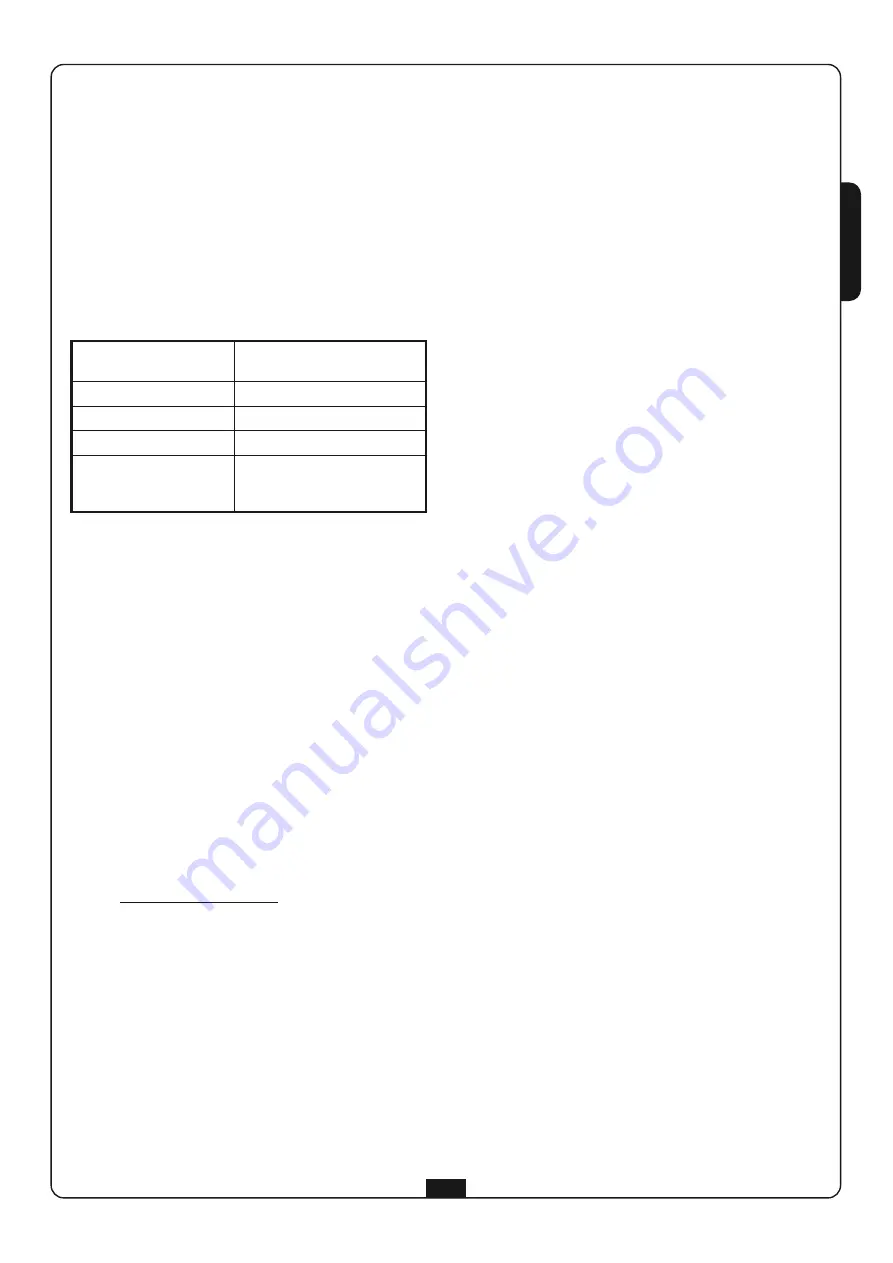
TECHNICAL SPECIFICATIONS

INSTALLATION OF THE SIRMO-DE and
SIRMO-DG RADIO VERSIONS

Ensure that the system is operating correctly prior to fixing the
digital switch (RADIO VERSION): 

1.

Open the device and insert the batteries provided, following 
the instructions given in parts 1,2,3,4 of the paragraph 
BATTERY REPLACEMENT

2.

Program the keypad and store a channel on the receiver (read 
the receiver instruction manual carefully).

3.

Position the keypad (without fixing it in place) and ensure 
that when the previously stored code is transmitted, the 
receiver activates the corresponding output.

4.

If the system is operating correctly, fix the keypad, otherwise, 
reduce the distance from the receiver in order for it to 
operate correctly.

!


PLEASE NOTE:  Avoid installation of the digital radio 

switch on metallic surfaces.

BATTERY REPLACEMENT

When the battery is run down, the device BEEPs and flashes for 2
seconds. The battery must be replaced. 
In this state, it is not possible to program the device.

To replace the battery, proceed as follows:

1.

Gently lever off the front panel 

A

using a flat-head 

screwdriver (Fig 2)

2.

Unscrew the 4 screws 

M

and extract the device 

C

from the 

base 

B

(Fig 1)

3.

Unscrew the 4 screws 

N

and remove the rear cover panel 

D

(Fig 1)

4.

Insert the batteries in the special housing observing the 
polarity marked on the battery cover (Fig 5)

!


PLEASE NOTE:  Only use 1.5 V – 1100 mAh AAA 

ALKALINE batteries.

SIRMO-DE

1.

Decide where the system should be installed, bearing in mind 
that the base must be fixed on a flat, straight surface.

2.

Gently lever off the front panel 

A

using a flat-head 

screwdriver (Fig 2)

3.

Unscrew the 4 screws 

M

and extract the device 

C

from the 

base 

B

(Fig 1)

4.

Fix the base onto the wall using appropriate raw plugs by 
means of the 4 through holes 

T

(Fig.4)

5.

Insert the device into the base and tighten the 4 screws 

M

(Fig 1)

6.

Insert the front panel

SIRMO-DG

1.

Remove the upper cap from the pillar.

2.

Position the device above the pillar, fix it in place using the 
screws 

O

supplied and insert the two caps 

P

(Fig. 3)

INSTALLATION OF THE SIRMO-DEC CABLED
VERSION

1.

Decide the layout of the cable trays for running the cables

2.

Decide where the system should be installed, bearing in mind 
that the base must be fixed on a flat, straight surface.

3.

Connect up the device (see the paragraph ELECTRICAL 
CONNECTIONS)

4.

Fix the base onto the wall using appropriate raw plugs by 
means of the 4 through holes 

(Fig 4)

5.

Insert the device into the base and tighten the 4 screws 

(Fig 1)

6.

Insert the front panel

INSTALLATION OF THE SIRMO-DGC CABLED
VERSION

1.

Remove the upper cap and the front glass from the pillar.

2.

Run the connecting cables up to the upper end of the pillar, 
passing them through the channelling behind the photocells.

3.

Insert the pillar front glass by running it downwards from 
above 

4.

Connect up the device (see the paragraph ELECTRICAL 
CONNECTIONS)

5.

Insert the device into the base and tighten the 4 screws 

(Fig 1)

6.

Insert the front panel

7.

Position the device above the pillar, fix it in place using the 
screws 

O

supplied and insert the two caps 

P

(Fig. 3)

ELECTRICAL CONNECTIONS

1.

Gently lever off the front panel 

A

using a flat-head 

screwdriver (Fig 2)

2.

Unscrew the 4 screws 

M

and extract the device 

C

from the 

base 

B

(Fig 1)

3.

Unscrew the 4 screws 

N

and remove the rear cover panel 

D

.

4.

Drill out the rear cover 

D

and insert the cable glands provided

5.

Pass the cables through the through hole 

H

and cable glands 

F

(Fig. 4)

6.

Close the rear cover 

D

with the 4 screw 

(Fig 1)

To connect one or more SIRMO-DEC devices to a V2 decoder,
follow the wiring diagram shown in Fig. 7

To connect a SIRMO-DEC device to a V2 control unit with data
input, follow the procedure indicated in the control unit
instruction manual.

Input 1 (N.C.) may be used for connection to a sensor for
indicating the status of the entrance (OPEN/CLOSED).
When the input is open, LED L2 is on.
If the input is not used, and it is desired to keep LED L2 off,
jumper terminal 1 (N.C.) with terminal 3 (GND).

Battery powered version

2 x 1,5V AAA alkaline 1100mAh

Cable powered version

12 / 24 Vac / dc

Radio power

< 1mW

Consumption

Max. 25mA  -  Min. 1µA

Battery lifetime

36500 transmissions
1 year with 100 transmissions 
per day

Summary of Contents for Sirmo-Digit Series

Page 1: ...Piemonte 65 67 12035 RACCONIGI CN ITALY tel 39 01 72 81 24 11 fax 39 01 72 84 050 info v2home com www v2home com SELETTORE DIGITALE DIGITAL SWITCH S LECTEUR DIGITAL SELECTOR DIGITAL SELECTOR DIGITAL...

Page 2: ...Fig 2 Fig 1...

Page 3: ...Fig 3 Fig 4 Fig 5 Fig 7...

Page 4: ...J1 ouvert 12 VCA VCC J1 cerrado 24 VCA VCC J1 abierto 3 GND GND GND GND 4 Codice Code Code C digo 5 Non utilizzato Not used Non utilis No se utiliza CONEX ES EL CTRICAS ELEKTRISCHE ANSCHL SSE ELEKTRI...

Page 5: ...dalla base B Fig 1 4 Fissare la base sulla parete con dei tasselli adeguati tramite i 4 fori T Fig 4 5 Inserire il dispositivo nella base e fissare le 4 viti M Fig 1 6 Inserire il frontalino SIRMO DG...

Page 6: ...digitato la trasmissione dura per tutto il tempo in cui il tasto o viene premuto e viene segnalata tramite dei BEEP IDENTIFICAZIONE DELLA MODALIT DI FUNZIONAMENTO Per identificare la modalit di funzi...

Page 7: ...per modificare le impostazioni del tastierino Il codice di fabbrica impostato 999999 Per garantire una maggior sicurezza del sistema si consiglia di personalizzare il codice di programmazione e di cus...

Page 8: ...cifre che sono 00 se il tasto memorizzato nel ricevitore il tasto 1 esempio 1010101010 00 10 se il tasto memorizzato nel ricevitore il tasto 2 esempio 1010101010 10 01 se il tasto memorizzato nel ric...

Page 9: ...propriate raw plugs by means of the 4 through holes T Fig 4 5 Insert the device into the base and tighten the 4 screws M Fig 1 6 Insert the front panel SIRMO DG 1 Remove the upper cap from the pillar...

Page 10: ...s transmit the same code independently of the access code entered transmission lasts for the entire time key or is pressed and is signalled by BEEPS IDENTIFICATION OF THE OPERATIONAL MODE To identify...

Page 11: ...unction each channel should be memorised in the receiver NOTE the possibility to use access codes made up by a unique digit therefore with the only identification digit of the channel makes the digita...

Page 12: ...plus 2 digits which are 00 if the key stored on the receiver is the key 1 e g 1010101010 00 10 if the key stored on the receiver is the key 2 e g 1010101010 10 01 if the key stored on the receiver is...

Page 13: ...sitif C de la base B Fig 1 4 Fixer la base au mur avec des tampons pr vus cet effet au moyen des 4 trous T Fig 4 5 Ins rer le dispositif dans la base et fixer les 4 vis M Fig 1 6 Ins rer le panneau de...

Page 14: ...pour tout le temps que la touche ou est press e et elle est signal e par des BIP IDENTIFICATION DE LA MODALIT DE FONCTIONNEMENT Pour identifier la modalit de fonctionnement configur e il suffit de pre...

Page 15: ...ation OPERATIONS A EFFECTUER SUR LE CLAVIER 1 Frapper CODE de PROGRAMMATION Signalisation 1 BEEP de 1 5 sec L1 et L2 allum s pour 1 5 sec 2 Frapper dans 1 minute la TOUCHE 1 Signalisation 1 BEEP L1 al...

Page 16: ...2 le code dip switch r gler correspond la position des 12 micro interrupteurs Si la touche m moris e dans l metteur est la 1 le code dip switch correspond la position des micro interrupteurs de 1 10...

Page 17: ...muro con dos tacos adecuados mediante los cuatro orificios T Fig 4 5 Inserte el dispositivo en la base y fije los cuatro tornillos M Fig 1 6 Inserte el frente SIRMO DG 1 Retire la tapa superior de la...

Page 18: ...te del c digo de acceso tecleado la transmisi n dura durante todo el tiempo en que la tecla o es pulsada y es se alada mediante BIPS IDENTIFICACI N DE LA MODALIDAD DE FUNCIONAMIENTO Para identificar l...

Page 19: ...digo de programaci n es 999999 Para garantizar una mayor seguridad del sistema aconsejamos personalizar el c digo de programaci n y guardarlo en un lugar seguro ATENCI N si se pierde el C DIGO DE PRO...

Page 20: ...zada en el receptor es la tecla 1 ejemplo 1010101010 00 10 si la tecla memorizada en el receptor es la tecla 2 ejemplo 1010101010 10 01 si la tecla memorizada en el receptor es la tecla 3 ejemplo 1010...

Page 21: ...arafusos M e extrair o dispositivo C da base B Fig 1 4 Fixar a base na parede com tacos adequados atrav s dos 4 furos T Fig 4 5 Inserir o dispositivo na base e fixar os 4 parafusos M Fig 1 6 Inserir a...

Page 22: ...do c digo de acesso digitado a transmiss o dura por todo o tempo em que a tecla ou permanece premida e assinalada atrav s dos BEEP IDENTIFICA O DA MODALIDADE DE FUNCIONAMENTO Para identificar a modali...

Page 23: ...Digitar C DIGO de PROGRAMA O Sinaliza es 1 BEEP de 1 5 seg L1 e L2 acesos por 1 5 seg 2 DiDigitar em at 1 minuto a TECLA 1 Sinaliza es 1 BEEP L1 aceso 3 Repetir o C DIGO de PROGRAMA O Sinaliza es 1 B...

Page 24: ...da no receptor a 2 o c digo dip switch a ser configurado corresponde posi o dos 12 microinterruptores Se a tecla memorizada no receptor a tecla 1 o c digo dip switch corresponde posi o dos microinterr...

Page 25: ...Ger t C von der Basis B abziehen Abb 1 4 Basis an der Wand mit den passenden D beln mit 4 L chern T befestigen Abb 4 5 Ger t in die Basis einsetzen und mit den 4 Schrauben befestigen 6 Frontabdeckung...

Page 26: ...e die bertragung dauert solange die Taste 1 oder gedr ckt wird und wird durch BEEP gemeldet ERKENNUNG DES BETRIEBSMODUS Zur Erkennung des eingestellten Betriebsmodus ist es ausreichend die Taste zu dr...

Page 27: ...ode einzustellen Die erste Ziffer des Codes identifiziert stets den Bezugskanal und kann nicht ver ndert werden Dies bedeutet dass es zum Beispiel nicht m glich ist dem Kanal 1 einen Zugangscode zuzuo...

Page 28: ...rte Taste 2 ist entspricht der einzustellende Dip Switch Code der Position der 12 Mikroschalter Wenn die am Empf nger gespeicherte Taste 1 ist entspricht der Dip Switch Code der Position der Mikroscha...

Page 29: ...aat C los van basis B Afb 1 3 Draai de 4 schroeven N los en verwijder achterdeksel D 4 Plaats de batterijen in het betreffende vak en neem de aanduidingen van de polen in acht die in de batterijhouder...

Page 30: ...d door de inschakeling van de leds L1 en L2 iedere toegangscode komt met een ander kanaal overeen PERSONAL PASS compatibiliteit met alle zenders met rolling code die bij 433 92 MHz een code van het ty...

Page 31: ...de zodat de handelingen vanaf het begin herhaald moet worden 2 TOEGANGSCODE De toegangscode is de combinatie die ingetoetst moet worden om de uitzending van de digitale code te activeren De in de fabr...

Page 32: ...nger bewaarde toets is de 2 dan komt de in te stellen dip switch code overeen met de positie van de 12 microschakelaars Is de in de ontvanger bewaarde toets de 1 dan komt de dip switch code overeen me...

Page 33: ......

Page 34: ......

Page 35: ......

Page 36: ......

Reviews: