E
N
G
L
IS
H
8
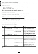
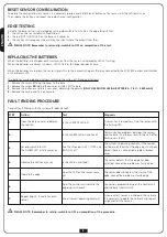
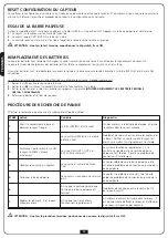
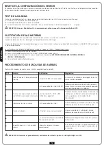
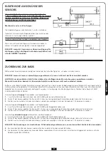
RESET SENSOR CONFIGURATION
To delete the configuration of a sensor, it is necessary to press and hold the SET button on the sensor until the LED remains on.
Then release the button and repeat the radio channel configuration.
EDGE TESTING
Activate the base unit testing method by setting dip-switch 8 to ON. Press the edge to verify that:
1.
the LED on the sensor remains fixed and on
2.
the red (OUT1/OUT2) LED on the base unit comes on
3.
The control unit recognises the alarm on the input where the output from the u
m
PLEASE NOTE: Remember to return dip-switch 8 to OFF on completion of the test.
REPLACING THE BATTERIES
When the batteries are charged, each transmission from the sensor is displayed by LED L3 flashing.
When the batteries are almost run down, LED L3 flashes for longer periods of time.
When the batteries are too low, the sensor signals this to the base which opens the relay connected to the LOW BAT output and switches
on the relevant LED.
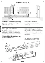
The batteries may be replaced without switching the system off. Proceed as follows:
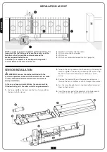
1.
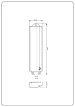
Remove the screw
O
fixing the cover to the base.
2.
Remove the screw
M
holding the cover and slide it off the base
3.
Remove the batteries and insert new ones, observing the polarity
(ONLY USE MODEL LR6/AA BATTERIES – 1.5 V – 2600 mAh)
4.
Reclose the casing and fix it once more.
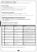
FAULT FINDING PROCEDURE
Conduct fault-finding with the system off (door closed).
m
PLEASE NOTE: Remember to set dip-switch 8 to OFF on completion of the procedure.
STEP
Action
Test
Diagnosis
1.
Open the base cover and observe
the red LED
Is the LOW BAT LED on?
A sensor has a low battery; find the sensor with
the flashing LED
2.
Is the ALARM LED on and fixed?
Communication problems between the sensors
and the base. Find the sensor with the LED off or
flashing very faintly
3.
Set dip switch 8 to ON:
the ALARM LED initially comes on
Are the three leds OUT1, OUT2 and
BAT LOW off?
The system is operating normally. If the control
unit does not show that the edge input has been
closed, there is a connection problem (broken
wire)
4.
Observe the LED for a sensor
Is the LED on and fixed?
The sensor detects that the edge has been
activated; connection problem or faulty edge
5.
Operate the edge
Does the LED on the sensor come
on?
The sensor does not detect the status of the
edge; connection problem or faulty edge
6.
-
Does the control unit indicate the
edge input is closed?
Connection problems between the control unit
and the base (short circuit)
7.
Repeat steps 4, 5 and 6 for each
sensor
Are all sensors operating normally?
A non-existent sensor is included in the network.
It is necessary to delete the network and repeat
assignment of the sensors


