background image

 Commissioning


6.2 

TZIDC-110 / TZIDC-120 


bieten 

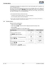
1.


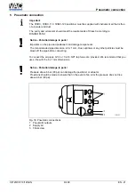
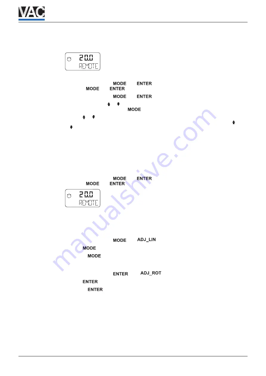
Feed in pneumatic auxiliary power 

2.


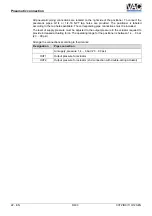
Connect the bus to the bus terminals with any polarity (or auxiliary power 9 ... 32 V DC), 

mA

%

C

°


is displayed 

3.


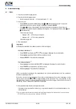
Check mount: 

•  Press and hold down 

 and 

. On completion of the countdown from 3 to 0, 

release 

 and 

. The unit switches to the operating level, mode 1.x 

•  Press and hold down 

 and 


• Additionally, 

press  or   until operating mode 1.3 (manual adjustment within the sensor 

range) is displayed. Release 


• Press  or   to move the actuator into the mechanical end position. Check the end 

positions. The rotation angle is displayed in degrees. For high-speed mode, press   and 

 simultaneously. 

Recommended range: 


-  between -28 ... 28° for linear actuators 


-  between -57 ... 57° for rotary actuators 


Minimum angle: 25° 


4.


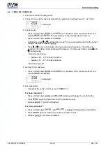
Go back to the bus level: 


•  Press and hold down 

 and 

. On completion of the countdown from 3 to 0, 

release 

 and 

mA

%

C

°


is displayed. 


5.


Run Autoadjust. 

•  Check that the unit is on the bus level ("REMOTE") 


For linear actuators 

1)

•  Press and hold down 

 until 

 is displayed. Release the control button 

• Press 

 again and hold down until the countdown ends 

• Release 

. This starts Autoadjust 


For rotary actuators 

1)

• 

Press and hold down 


 until 

 is displayed. Release the control button 

• 

Press 

 again and hold down until the countdown ends 

• 

Release 

. This starts Autoadjust 

CI/TZIDC/110/120-EN 

                                                  D400

EN - 25 

Summary of Contents for D400

Page 1: ......

Page 2: ...905 534 Fax 49 551 905 555 CCC support deapr de abb com Copyright 2009 by ABB Automation Products GmbH Subject to changes without notice This document is protected by copyright It assists the user in...

Page 3: ...g on rotary actuators 14 4 Electrical connection 17 4 1 Screw terminal assignments 18 4 2 Jumper configuration on mainboard TZIDC 120 only 19 4 3 Cable entry 20 5 Pneumatic connection 21 6 Commissioni...

Page 4: ...Contents CI TZIDC 110 120 EN D400 EN 3 7 3 4 CSA Certification Record 44 7 3 5 FM Approvals 45...

Page 5: ...ft the factory in a safe maintenance free state The information in the manual must be observed and followed in order to maintain this state throughout the period of operation Modifications and repairs...

Page 6: ...rts coming into contact with the materials to be measured ABB Automation Products GmbH will gladly support you in selecting the materials but cannot accept any liability in doing so The operators must...

Page 7: ...njury WARNING Bodily injury This symbol in conjunction with the signal word Warning indicates a potential electrical hazard Failure to observe this safety information may result in death or severe inj...

Page 8: ...s that may be accessed by unauthorized persons take the required protective measures 2 Ex relevant safety instructions Depending on the type of explosion protection an Ex label is attached to the left...

Page 9: ...st before restoring factory settings 3 1 Operating conditions at installation site Important Before installation check whether the D400 positioner meets the control and safety requirements for the ins...

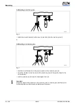
Page 10: ...or linear actuators 4 Operating range for rotary actuators Important During installation make sure that the actuator travel or rotation angle for position feedback is implemented correctly The maximum...

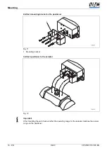
Page 11: ...ear actuators Lever 4 with follower pin for stroke adjustment 10 35 mm 0 39 1 38 inch or 20 100 mm 0 79 3 94 inch Follower guide 13 with two screws 10 spring washers 11 and clamp plates 12 Mount brack...

Page 12: ...er moves within the operating range between the arrows Hand tighten the screw 7 on the lever Hold the prepared positioner with loose mount bracket 1 to the actuator so that the follower pin for the le...

Page 13: ...he proper position on the columnar yoke 2 Insert the U bolts 1 from the inside of the columnar yoke 2 through the holes for the mount bracket Add the washers 4 and nuts 5 Hand tighten the nuts Importa...

Page 14: ...or the position sensor Moving the link point inward increases the rotation angle of the sensor Moving the link point outward reduces the sensor s rotation angle Adjust the actuator stroke to make use...

Page 15: ...ng kit is available Fig 9 Adapter 1 with spring 5 each four screws M6 4 spring washers 3 and shim 2 to attach the mounting bracket 6 on the positioner each four screws M5 7 spring washers 8 and shim 9...

Page 16: ...the actuator determine in which position the feedback shaft 1 for the positioner must be pre adjusted and in which position the adapter 2 must be placed to enable the positioner to travel within the p...

Page 17: ...e positioner Fig 11 1 Mounting bracket 3 Attach positioner to the actuator Fig 12 Important After mounting the unit check whether the operating range for the actuator matches the sensor range on the p...

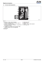
Page 18: ...ches insert the wire ends from the left into the respective screw terminals and hand tighten the screws access from above To connect a plug in module insert the wire ends from above in the appropriate...

Page 19: ...of emergency shutdown module 3 Module for digital position feedback 1 or terminals of the shutdown module 4 Installation kit for digital position feedback either proximity switches or 24 V microswitch...

Page 20: ...re two jumpers on the mainboard that can be used to activate or block simulation mode and write access Set the jumpers as shown below M00495 1 2 Fig 16 1 Block Simulation blocked 1 2 Activate Write ac...

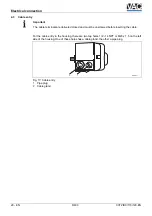
Page 21: ...ust be unscrewed before inserting the cable For the cable entry in the housing there are two tap holes 1 2 14 NPT or M20 x 1 5 on the left side of the housing One of these holes has a cable gland the...

Page 22: ...mended pipe dimension is 6 x 1 mm Dust splinters or any other particles must be blown off the pipe before connecting To connect the air pipes G1 4 or 1 4 18 NPT tap holes are provided We recommend tha...

Page 23: ...rresponding pipe connections must be included The level of supply pressure must be adjusted to the output pressure in the actuator required to provide increased actuating force The operating range for...

Page 24: ...tdown ends Release This starts the Autoadjust For rotary actuators 1 Press and hold until is displayed Release the control button Press and hold till the countdown ends Release This starts the Autoadj...

Page 25: ...1 without adaptation the control parameter conf mA C conf mA C 1 2 Manual adjustment 2 in the operating range Adjust via or 3 conf mA C conf mA C 1 3 Manual adjustment 2 in the sensor range Adjust via...

Page 26: ...e rotation angle is displayed in degrees For high speed mode press and simultaneously Recommended range between 28 28 for linear actuators between 57 57 for rotary actuators Minimum angle 25 4 Go back...

Page 27: ...rmal circumstances 1 The zero position is determined automatically and saved during Autoadjust counter clockwise CTCLOCKW for linear actuators and clockwise CLOCKW for rotary actuators 6 2 1 Operating...

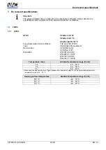
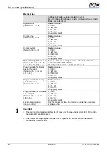
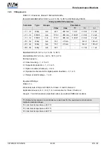
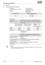
Page 28: ...ficate T V 04 ATEX 2702 X Type Intrinsically safe equipment Device class II 2G EEx ia IIC II 2G Eex ib IIC Standards EN 60079 0 2006 EN 60079 11 2007 EN 61241 0 2006 EN 61241 11 2006 Temperature class...

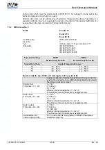
Page 29: ...00 ATEX 2049 X Proximity switches manuf by Pepperl Fuchs Plug in module for digital position feedback Terminal 51 52 or 41 42 Maximum values Ui 30 V Ii 320 mA Pi 500 mW Ci 3 7 nF Li negligibly small...

Page 30: ...Ex nA IIC resp Ex nL IIC Temperature Class Ambient temperature range T4 40 85 C 40 85 C T5 40 50 C 40 65 C T6 40 40 C 40 50 C Electrical data for type TZIDC with marking Ex ia IIC resp Ex ib IIC In ty...

Page 31: ...nF The effective internal inductance is negligibly small Notice The intrinsically safe circuits are galvanically separated up to a voltage of 60 V The local communication interface LKS is connected w...

Page 32: ...20 mA Max output pressure 90 psi Max ambient 85 Deg C Class I Div 1 Groups A B C and D Class II Div 1 Groups E F and G Class III Enclosure Type 4X Model TZIDC P N V18345 x0x2x2xx0x Intelligent Positi...

Page 33: ...ture Code T4 Max Ambient 85 Deg C Notice The x in P N denotes minor mechanical variations or optional features Do not use the local communication interface LKS in hazardous areas Each pair of conducto...

Page 34: ...6 6 nF Li 0 uH Terminals 81 82 V max 30 V I max 110 mA Ci 3 7 nF Li 0 uH Terminals 83 84 V max 30 V I max 96 mA Ci 3 7 nF Li 0 uH Terminals 31 32 V max 30 V I max 110 mA Ci 6 6 nF Li 0 uH Terminals 41...

Page 35: ...ply ia ib for Grp IIB IIC Voltage 17 5 V 17 5 V 24 V Current 380 mA 360 mA 250 mA Power 5 32 W 2 52 W 1 2 W Characteristic rectangular trapezoidal linear Li negligibly small Ci negligibly small In int...

Page 36: ...C Electrical data for type TZIDC 110 with marking Ex ia IIC T6 resp Ex ib IIC T6 Input circuit terminals 11 12 or In type of protection Intrinsic Safety Ex ia IIC resp Ex ib IIC only for the connectio...

Page 37: ...circuits are galvanically separated up to a voltage of 60 V The local communication interface LKS and program interface X5 are connected with the signal circuit Electrical data for type TZIDC 110 wit...

Page 38: ...ELV circuit Intrinsically safe with entity parameters of Terminals 11 12 V max 24 V I max 250 mA Ci 2 8 nF Li 7 2 uH Terminals 85 86 U max 30 V I max 50 mA Ci 3 8 nF Li 0 uH Terminals 41 42 U max 16 V...

Page 39: ...a SELV Circuit Intrinsically safe with entity parameters of Terminals 11 12 V max 24 V I max 250 mA Ci 2 8 nF Li 7 2 uH Terminals 85 86 U max 30 V I max 50 mA Ci 3 8 nF Li 0 uH Terminals 41 42 U max...

Page 40: ...2 ABCD T6 T5 T4 Ta 40 C 55 C 85 C S II III 2 EFG T6 T5 T4 Ta 40 C 55 C 85 C Enclosure type 4x a Case mounting 1 2 5 or 6 b Output safe protection 1 2 4 or 5 c Option modules shutdown 0 or 4 d Optiona...

Page 41: ...upply ia ib for Grp IIB IIC Voltage 17 5 V 17 5 V 24 V Current 380 mA 360 mA 250 mA Power 5 32 W 2 52 W 1 2 W Characteristic rectangular trapezoidal Linear Li negligibly small Ci negligibly small In i...

Page 42: ...C Electrical data for type TZIDC 120 with marking Ex ia IIC T6 resp Ex ib IIC T6 Input circuit terminals 11 12 or In type of protection Intrinsic Safety Ex ia IIC resp Ex ib IIC only for the connectio...

Page 43: ...circuits are galvanically separated up to a voltage of 60 V The local communication interface LKS and program interface X5 are connected with the signal circuit Electrical data for type TZIDC 120 wit...

Page 44: ...ELV circuit Intrinsically safe with entity parameters of Terminals 11 12 V max 24 V I max 250 mA Ci 2 8 nF Li 7 2 uH Terminals 85 86 U max 30 V I max 50 mA Ci 3 8 nF Li 0 uH Terminals 41 42 U max 16 V...

Page 45: ...a SELV Circuit Intrinsically safe with entity parameters of Terminals 11 12 V max 24 V I max 250 mA Ci 2 8 nF Li 7 2 uH Terminals 85 86 U max 30 V I max 50 mA Ci 3 8 nF Li 0 uH Terminals 41 42 U max...

Page 46: ...D T6 T5 T4 Ta 40 C 55 C 85 C S II III 2 EFG T6 T5 T4 Ta 40 C 55 C 85 C Enclosure type 4x a Case mounting 1 2 5 or 6 b Output safe protection 1 2 4 or 5 c Option modules shutdown 0 or 4 d Optional mech...

Page 47: ...Ex relevant specifications 46 EN TZIDC TZIDC 110 TZIDC 120 CI TZIDC 110 120 EN...

Page 48: ...ols Inc 200 Jade Park Chelsea AL 35043 TEL 205 678 0507 FAX 205 678 0510 vacaccessories com Valve Accessories Controls Inc 12942 Bedford Falls Dr Cypress TX 77429 TEL 713 253 7781 FAX 281 256 9399 ran...

Reviews: