30
… 7 Installation
… Electrical connections
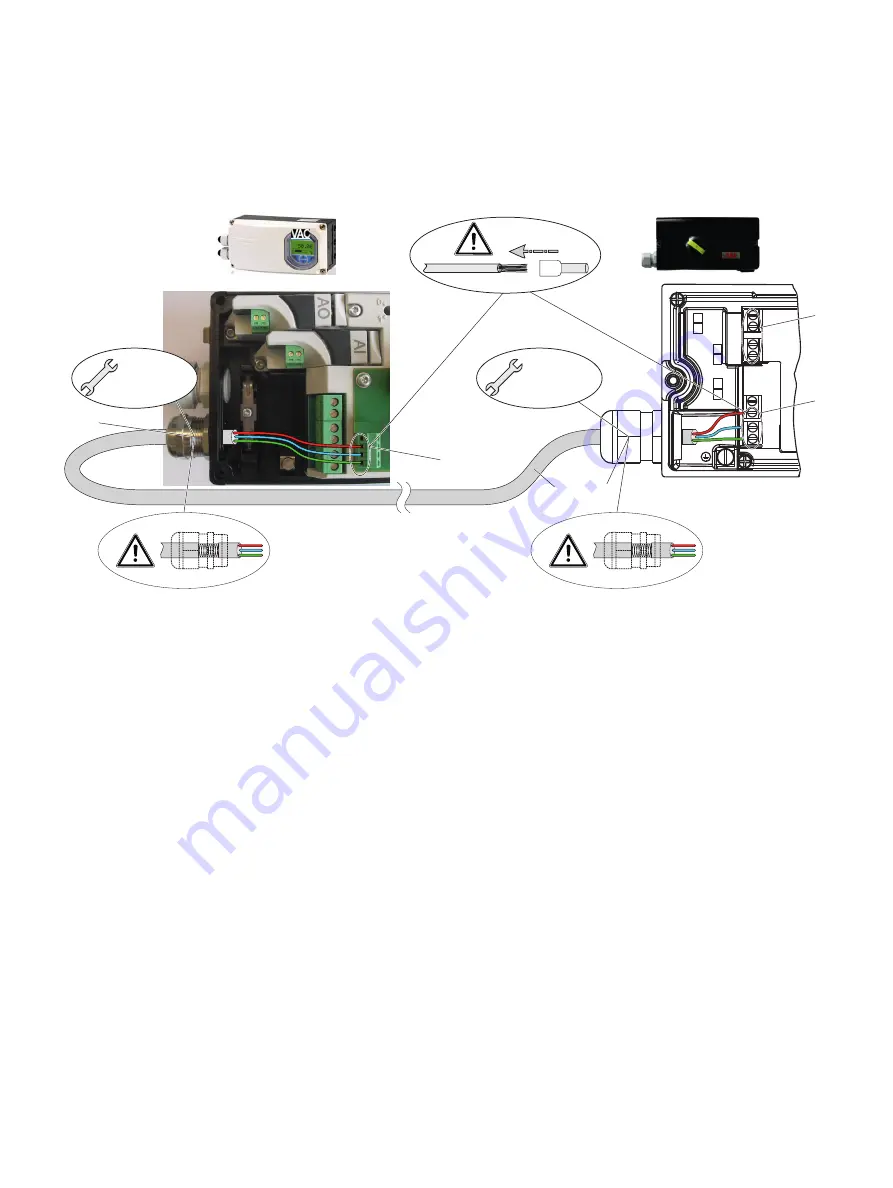
Connection to device - EDP300 Control Unit with EDP300 Remote Sensor
Housing 1 (EDP300 Control Unit)
Housing 2 (EDP300 Remote Sensor)
M10832-01
+41 -42
Limit 2
Limit 1
+51 -52
1 2 3
1
1
4
3
3
2
M 20 mm /
NPT 1/2"
M 20 mm /
NPT 1/2"
1
Terminals EDP300 Remote Sensor
2
Terminal attachment kit for digital feedback
3
EMC Cable gland
4
Shielded connection cable
Figure 23: Connection EDP300 Control Unit with EDP300 Remote Sensor (example)
Change from one to two columns
In the case of the ‘EDP300 Control Unit with EDP300 Remote
Sensor’ design, the components are supplied in two housings,
which together form one harmonized unit.
Housing 1 (EDP300 Control Unit) contains the electronics and
pneumatics along with the following optional modules (where
applicable):
•
Analog position feedback
•
Digital position feedback
•
Emergency shutdown module
•
Universal
input
Housing 2 (EDP300 Remote Sensor) contains the position sensor
and is suitable for mounting on linear or rotary actuators.
If necessary, the following options can be installed if required:
•
Optical position indicator
•
Mechanical
feedback
contacts designed as proximity
switches or microswitches.
The housings of the EDP300 Control Unit and the EDP300
Remote Sensor are available in stainless steel as an option.
Cable specification
To connect the EDP300 Remote Sensor, a cable with the
following specifications needs to be used:
•
3-wire, cross-section 0.5 to 1.0 mm²
•
Shielded, with at least 85 % coverage
•
Temperature range up to at least 100 °C (212 °F)
The cable glands used must also be approved for a temperature
range up to at least 100 °C (212 °F). The cable glands require a
mounting for the shielding and strain relief for the cable in
addition.
ABB offers suited cables and cable glands with DNV_GL
certification for the EDP300 Remote Version.
Summary of Contents for D500
Page 82: ...82 17 Appendix Control Drawing 901305...
Page 83: ...83...
Page 84: ...84 17 Appendix Control Drawing 901305...
Page 85: ...85...
Page 86: ...86 17 Appendix Control Drawing 901305...
Page 87: ...87...


