background image

6

GENERAL ASSEMBLY INSTRUCTIONS

W A R N I N G :     T O   R E D U C E   T H E   R I S K   O F   E L E C T R I C   S H O C K ,   D O   N O T   E X P O S E   T O   R A I N .    

M A K E   S U R E   P L U G   I S   D I S C O N N E C T E D   B E F O R E   A S S E M B L I N G   T H E   W E T / D R Y   V A C .

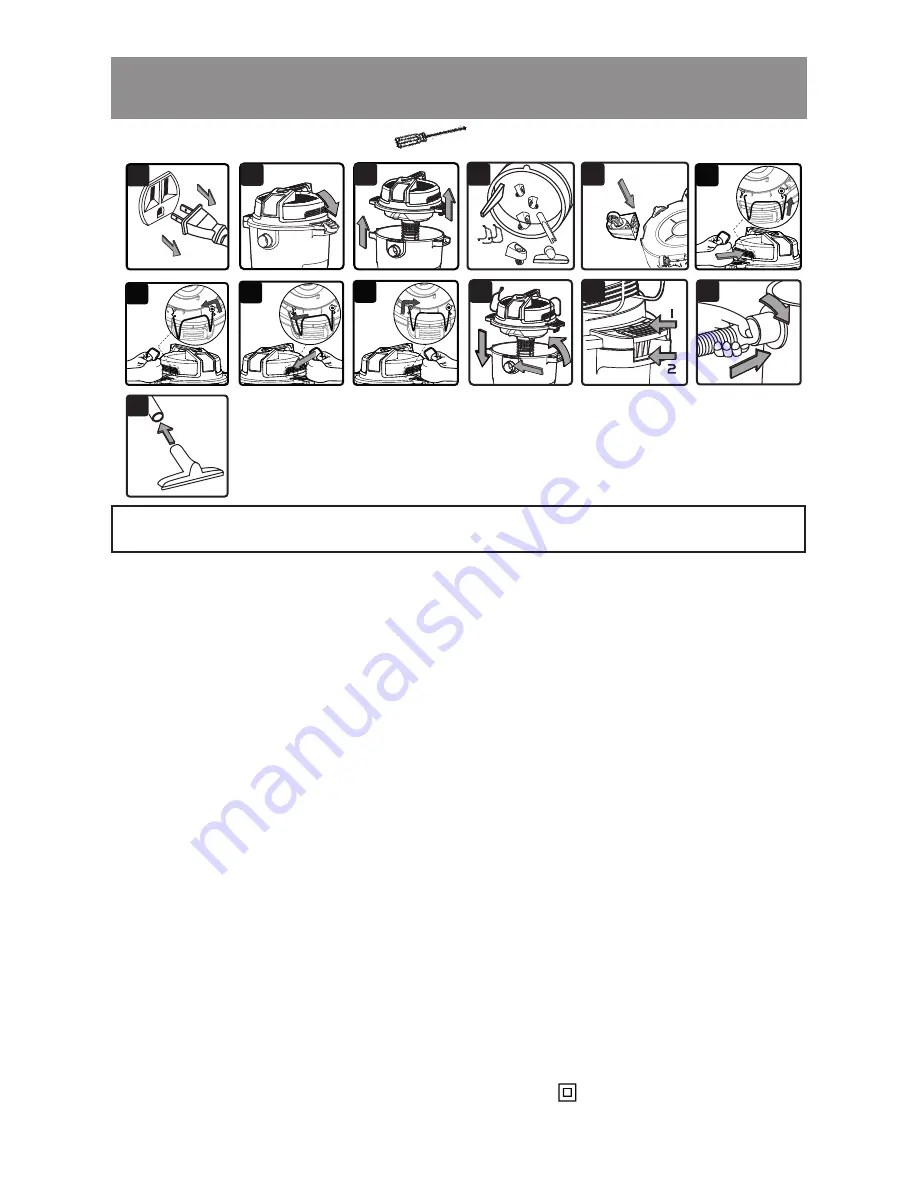
  1.  Verify that the power cord is disconnected from the outlet.  (Fig. 1)

  2.  Undo the latches.  (Fig. 2)

  3.  Lift the power head off the collection tank.  (Fig. 3)

  4 .   Remov e the contents from inside the collection tank;  make sure y ou hav e all contents as listed 

on page 5.  (Fig. 4)

  5.  Turn the collection tank upside down and insert the four caster feet into the slots on the 

collection tank and tighten with supplied screws.  Verify that the casters are mounted correctly.  

Do not over-tighten screws.  (Fig. 5)

  6.  Position the hose storage rack as illustrated.  Fully insert one end of the hose storage rack 

into the slot illustrated by the arrow, then pull the other end of the hose storage rack to align 

with the corresponding arrow and insert into the slot until it is secured in place.  (Fig. 6a - 6d)

  7 .   Y our va cuum comes ready  for dry  va cuum cleaning.   For installation instructions,  see p age 1 1 .

  8.  For wet vacuum cleaning, install the supplied foam wet filter.  See page 12 for filter installation. 

  9.  Place the power head back on the collection tank, and secure into place using the 2 side 

latches.  (Fig. 7 & 8)

1 0 .   I nsert the locking end of the hose into the p ort on the collection tank and turn to lock into 

place.  (Fig. 9)

11.  Choose the desired accessory and insert onto the end of the hose.  (Fig. 10)

N O I S E   D I F F U S E R

For quiet operation, install the noise diffuser into the blower port by inserting the locking end of the 

diffuser into the blower port and turning clockwise to lock into place.

P O L A R I Z E D   P L U G

To reduce the risk of electrical shock, this appliance has a polarized plug (one blade wider than 

the other).   This plug will fit in a polarized outlet only one way.   If the plug does not fit fully in the 

outlet, reverse the plug.   If it still does not fit, contact a qualified electrician to install the proper 

outlet.   Do not change the plug in any way.   Double insulation       eliminates the need for the 

three wire grounded power cord and grounded power supply system.

A Philips head screw driver is required.

1

10

3

8

9

2

5

4

  7

6 d

6 a

6 b

6 c

U N P A C K I N G   Y O U R   W E T / D R Y   V A C U U M   &   G E N E R A L   A S S E M B L Y

Summary of Contents for VJH1211PF 0201

Page 1: ...e n v i l l e S C 29 6 0 7 Rep lacement Filters A ccessories ava ilab le at V a c m a s t e r c o m F O R Y O U R S A F E T Y Read and understand this manual b efore use K eep this manual for future reference 12 G a l l o n M odel N o V J H 1211P F 0 20 1 O p e r a t o r s M a n u a l W e t D r y V a c u u m ...

Page 2: ...exterior finish due to use or exposure Any product where serial number data label is tampered with or removed Any product purchased from an unauthorized retailer TABLE OF CONTENTS WARRANTY W arranty 2 Safety I nstructions W arnings 3 Doub le I nsulation I nstructions 4 E xt ension Cords 4 U np acking Checking Carton Contents 5 G eneral A ssemb ly I nstructions 6 Dry Vacuum Op eration 7 Liq uid Vac...

Page 3: ... been dropped damaged left outdoors or dropped into water return it to a service center Do not p ull or carry b y cord use cord as handle close a door on cord or p ull cord around sharp edges or corners Do not run W et Dry Vac ove r cord Do not handle plug or the Wet Dry Vac with wet hands To reduce the risk of health hazards from vapors or dusts do not vacuum toxic materials Do not use or store n...

Page 4: ...U N D I N G N O T R E Q U I R E D W H E N S E R V I C I N G U S E O N L Y I D E N T I C A L R E P L A C E M E N T P A R T S W A R N I N G T O R E D U C E T H E R I S K O F E L E C T R I C S H O C K D O N O T E X P O S E T O R A I N S T O R E I N D O O R S W A R N I N G S E R V I C I N G O F D O U B L E I N S U L A T E D W E T D R Y V A C U U M W I T H A D O U B L E I N S U L A T E D W E T D R Y V ...

Page 5: ... t e n t s L i s t A B C D E F G H I K J L M UNPACKING CHECKING CARTON CONTENTS K ey Descrip tion Q ty A Vac A ssemb ly 1 B Hose 1 C E xt ension W ands 2 D Utility Nozzle 1 E Crevi ce Tool 1 F Floor Nozzle 1 G Foam W et Filter 1 H Cartridge Filter 1 I N oise Diffuser 1 J 4 Screws Bag 1 K Caster Foot A ssemb ly 4 L Hose Storage Rack 2 M Op erator s M anual 1 Blower Port Handle Collection Tank Latch...

Page 6: ...or installation instructions see p age 1 1 8 For wet vacuum cleaning install the supplied foam wet filter See page 12 for filter installation 9 Place the power head back on the collection tank and secure into place using the 2 side latches Fig 7 8 1 0 I nsert the locking end of the hose into the p ort on the collection tank and turn to lock into place Fig 9 11 Choose the desired accessory and inse...

Page 7: ...D V A C U U M I N G DRY VACUUM OPERATION W A R N I N G B E S U R E T O R E A D U N D E R S T A N D A N D A P P L Y I N F O R M A T I O N E N T I T L E D S A F E T Y I N S T R U C T I O N S W A R N I N G S D O N O T V A C U U M I N A R E A S W I T H F L A M M A B L E G A S E S V A P O R S O R E X P L O S I V E D U S T S I N T H E A I R F L A M M A B L E G A S E S O R V A P O R S I N C L U D E B U T...

Page 8: ...U S E T H E C A R T R I D G E F I L T E R F O R L I Q U I D V A C U U M I N G O P E R A T I N G I N S T R U C T I O N S W E T V A C U U M I N G 3 Fit the desired nozzle to the vacuum hose Fig 2 4 Verify that the power switch is in the O OFF position before plugging the power cord into the outlet Fig 3 5 Turn the motor on by pressing the switch to the I ON position Fig 4 6 Once you have completed v...

Page 9: ...disconnected from the outlet Fig 1 2 Make sure the collection tank is empty before using as a blower 3 Remove hose from the vacuum port Remove noise diffuser from blower port 4 Insert the larger end of the hose into the blower port on the back side of the power head and lock into place Fig 2 5 Fit the desired attachment to the hose Fig 3 6 Verify that the power switch is in the O OFF position befo...

Page 10: ...k the hose attachments and power cord to verify that they have not been damaged 7 Place power head on collection tank and secure latches I M P O R T A N T Clean or change the cartridge filter regularly for best performance A L W A Y S U S E C A R T R I D G E F I L T E R F O R D R Y V A C U U M I N G If the machine is used without the cartridge filter the motor will burn out and the warranty will b...

Page 11: ... Clean the cartridge filter by gently tapping or brushing dirt off Cleaning should not be done indoors in living areas For optimal performance a new filter is recommended 4 Install cleaned or new filter into place as above in steps 2 and 3 of Installing Cartridge Filter 5 Wet filters should be removed and allowed to air dry for 24 hours before installing onto the filter cage I M P O R T A N T Clea...

Page 12: ...nlet The cartridge filter is clogged by fine dust 1 Check nozzle hose and collection tank inlets for b lockage Take off the filter and clean it or install a new cartridge filter I n s t a l l i n g F o a m W e t F i l t e r 1 Verify that the power cord is disconnected from the outlet Fig 1 2 Remove power head and place in upside down position Follow instructions to remove cartridge filter 3 Carefu...

Page 13: ...1 3 EXPLODED VIEW ...

Page 14: ...7 Vaccum Port Assembly 1 7 551006106 Vacuum Port Cover 1 8 551002110 Drain Cap A ssemb ly 1 9 551006109 Caster Foot A ssemb ly 4 1 0 551004104 Filter Retainer 1 1 1 VCFF Cartridge Filter 1 1 2 551060104 E VA Hose 1 1 3 V2 E W E xt ension W ands 2 1 4 V2 FBS Floor Nozzle 1 15 V2 CT Crevi ce Tool 1 1 6 V2 U N Utility Nozzle 1 1 7 551002117 N oise Diffuser 1 1 8 VFF51 Foam W et Filter 1 ...

Reviews: