background image

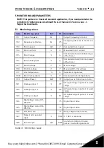
monitoring & parameters

vacon 

 27

5

NOTE!

 These parameters are shown, when P17.2 = 0.

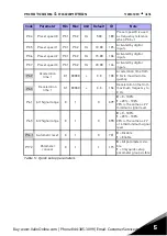
 Brake Chopper

0

2

0

504

= Disabled

= Enabled: Always

= Run state

 Brake chopper 

level

0

911

V

varies

1267

Brake chopper control acti-
vation level in volt.
For 240V Supply: 
240*1.35*1.18 = 382V
For 400V Supply: 
400*1.35*1.18 = 638V
Please note that when 
brake chopper is used the 
overvoltage controller can 
be switched off or the over-
voltage reference level can 
be set above the brake 
chopper level.

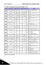
Motor 

identification

0

1

0

631

0

 = Not active

1

 = Standstill identification 

(need run command within 
20 s to activate) 

Rs voltage drop

0.00 100.00

%

0.00

662

Voltage drop over motor 
windings as % of U

nmot

 at 

nominal current.

Overvoltage 

controller

0

2

1

607

= Disabled

= Enabled, Standard 

mode

= Enabled, Shock load 

mode

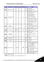
Undervoltage 

controller

0

1

1

608

0

 = Disable

1

 = Enable

Sine filter

0

1

0

522

0

 = Not in use 

1

 = In use

Modulator type

0

65535

28928

648

Modulator configuration word: 

B1

 = Discontinuous modu-

lation (DPWMMIN) 

B2

 = Pulse dropping in 

overmodulation 

B6

 = Under modulation 

B8

 = Instantaneous DC volt-

age compensation * 

B11

 = Low noise 

B12

 = Dead time compensation * 

B13

 = Flux error compensation * 

* Enabled by default 

Code

Parameter

Min

Max

Unit

Default

ID

Note

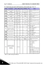
Table 6: Motor settings

P1.17

P1.18

P1.19

P1.20

P1.21

P1.22

P1.23

P1.24

Buy: www.ValinOnline.com | Phone 844-385-3099 | Email: CustomerService@valin.com

Summary of Contents for 20 SERIES

Page 1: ...vacon 20 ac drives quick guide Buy www ValinOnline com Phone 844 385 3099 Email CustomerService valin com...

Page 2: ...Buy www ValinOnline com Phone 844 385 3099 Email CustomerService valin com...

Page 3: ...om the mains poten tial However the relay output terminals may have a danger ous control voltage present even when Vacon 20 is disconnected from mains The earth leakage current of Vacon 20 frequency c...

Page 4: ...2 vacon safety 1Buy www ValinOnline com Phone 844 385 3099 Email CustomerService valin com...

Page 5: ...w or DIN rail mounting For MI4 MI5 screw or flange mounting Figure 1 Screw mounting MI1 MI3 Figure 2 Screw mounting MI4 MI5 M5 MI3 MI1 M4 MI2 M5 LOC REM BACK RESET OK LOC REM BACK RESET OK LOC REM BAC...

Page 6: ...g above 100 mm below 50 mm and on the sides 20 mm of Vacon 20 For MI1 MI3 side to side installation allowed only if the am bient temperature is below 40 C For MI4 MI5 side to side installation is not...

Page 7: ...mounting cutout dimensions for MI4 Unit mm Figure 6 Flange mounting cutout dimensions for MI5 Unit mm Drive outline Opening outline Drive outline Opening outline Buy www ValinOnline com Phone 844 385...

Page 8: ...6 vacon installation 2 Figure 7 Flange mounting depth dimensions for MI4 and MI5 Unit mm M15 M14 Buy www ValinOnline com Phone 844 385 3099 Email CustomerService valin com...

Page 9: ...PE plate and API cable support MI4 MI5 Attach this plate BEFORE installing the power cables Attach the support AFTER installing the power cables Attach the support AFTER installing Attach this plate B...

Page 10: ...Vacon 20 power connections MI2 MI3 1 230V 3 230V 400V Motor out MAINS MOTOR Strip the plastic cable coating for 360 earthing L1 L2 N L3 U T1 V T2 W T3 R R 1 230V 3 230V 400V 575V 1 115V MAINS MOTOR BR...

Page 11: ...20 power connections MI4 Figure 13 Vacon 20 power connections MI5 MAINS MOTOR Motor out Brake RESISTOR 3 380 480V MAINS MOTOR Motor out Brake RESISTOR 3 380 480V Buy www ValinOnline com Phone 844 385...

Page 12: ...10 vacon installation 2 2 2 2 Control cabling Figure 14 Open the lid MI1 MI3 Figure 15 Open the lid MI4 MI5 Buy www ValinOnline com Phone 844 385 3099 Email CustomerService valin com...

Page 13: ...all the control cables MI1 MI3 Figure 17 Install the control cables MI4 MI5 Strip the plastic cable coating for 360 earthing Control cable tightening torque 0 4 Nm Buy www ValinOnline com Phone 844 38...

Page 14: ...boards in Vacon20 See below for the allowed option boards in the slot Note OPT B1 and OPT B4 only support external power supply Option board assembly structure 6 27 1 2 3 Buy www ValinOnline com Phone...

Page 15: ...installation vacon 13 2 4 5 6 Buy www ValinOnline com Phone 844 385 3099 Email CustomerService valin com...

Page 16: ...14 vacon installation 2 Buy www ValinOnline com Phone 844 385 3099 Email CustomerService valin com...

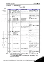
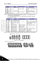
Page 17: ...250 Other 0 10 V Ri 200 k Selectable through micro switch 5 GND I O signal ground 13 DO Digital Output Common Digital Output Common 14 DI4 Digital input 4 Preset speed B0 P 18 30 V Ri 5 k 15 DI5 Digi...

Page 18: ...reset P 14 DI4 Digital input 4 Preset speed B0 P 18 30 V Ri 5 k 15 DI5 Digital input 5 Preset speed B1 P Only for DI 16 DI6 Digital input 6 External Fault P Only for DI Table 2 DI Sink Type remove ju...

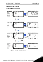
Page 19: ...M S TO P RE AD Y RUN MO N FWD RE V I O KE YP AD BU S REF PAR FAULT ALAR M S TO P RE ADY RU N MO N FW D RE V I O KE YP AD BUS R EF PAR FAU LT ALAR M STO P READ Y RU N MO N PRESS PRESS PRESS PRESS PRESS...

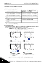
Page 20: ...ooling air 9 Perform an identification run Par ID631 4 Check that all start stop switches are in STOP position 10 Connect the motor to the process and per form test run once again 5 Connect the drive...

Page 21: ...FWD REV I O KEY PAD BUS FWD REV I O KEY PAD BUS FWD REV I O KEY PAD BUS READ Y RUN STOP ALARM FAU LT REF MON PAR SYS REF MON PAR SYS READ Y RUN STOP ALARM FAU LT REF MON PAR SYS FWD REV I O KEY PAD BU...

Page 22: ...20 vacon navigation startup 4Buy www ValinOnline com Phone 844 385 3099 Email CustomerService valin com...

Page 23: ...Motor voltage V 6 Motor voltage V1 8 DC link voltage V 7 Measured DC link voltage V1 9 Unit temperature C 8 Heatsink temperature V1 10 Motor temperature 9 Calculated motor temperature V1 11 Output Pow...

Page 24: ...value shows status of the relay outputs 1 3 from option board hidden until an option board is connected V2 17 DOE4 DOE5 DOE6 36 This monitor value shows status of the relay outputs 4 6 from option bo...

Page 25: ...ive B8 Local Control Active B9 PC Control Active B10 Preset Frequencies Active V3 3 DIN status word 56 B0 DI1 B1 DI2 B2 DI3 B3 DI4 B4 DI5 B5 DI6 B6 DIE1 B7 DIE2 B8 DIE3 B9 DIE4 B10 DIE5 B11 DIE6 V4 1...

Page 26: ...it 107 Maximum motor current Torque boost 0 1 0 109 0 Not used 1 Used P2 1 Remote control place 1 selection 0 2 0 172 0 I O terminal 1 Fieldbus 2 Keypad Start function 0 1 0 505 0 Ramp 1 Flying start...

Page 27: ...o maximum fre quency Deceleration time 1 0 1 3000 0 s 3 0 104 Deceleration time from maximum frequency to 0 Hz P6 1 AI1 Signal range 0 1 0 379 0 0 100 1 20 100 20 is the same as 2 V minimum signal lev...

Page 28: ...0 0 Frequency control 1 Open loop speed control U f ratio 0 2 0 108 0 Linear 1 Square 2 Programmable Field weakening point 8 00 320 00 Hz 50 00 60 00 602 Field weakening point fre quency Field weakeni...

Page 29: ...activate Rs voltage drop 0 00 100 00 0 00 662 Voltage drop over motor windings as of Unmot at nominal current Overvoltage controller 0 2 1 607 0 Disabled 1 Enabled Standard mode 2 Enabled Shock load m...

Page 30: ...2 0 Forward Reverse 1 Fwd edge Inverted Stop 2 Fwd edge Bwd edge 3 Start Reverse 4 Start edge Reverse P2 5 Local Remote 0 1 0 211 0 Remote control 1 Local control P2 6 Keypad control direction 0 1 0...

Page 31: ...en P3 3 1 P3 5 Preset speed 1 P3 1 P3 2 Hz 10 00 105 Activated by digital inputs P3 6 Preset speed 2 P3 1 P3 2 Hz 15 00 106 Activated by digital inputs P3 7 Preset speed 3 P3 1 P3 2 Hz 20 00 126 Activ...

Page 32: ...1 3000 0 s 10 0 503 See the parameter P4 3 Flux Braking 0 3 0 520 0 Off 1 Deceleration 2 Chopper 3 Full Mode Flux Braking Current 0 5 x INunit 2 0 x INunit A INunit 519 Defines the current level for f...

Page 33: ...uency limit 0 00 P3 2 Hz 1 00 1539 Close frequency from positive direction if no run command active P4 18 External Brake Close Frequency limit in Reverse 0 00 P3 2 Hz 1 50 1540 Close frequency from ne...

Page 34: ...set 0 Varies 3 414 See 5 1 P5 7 Run enable 0 Varies 0 407 See 5 1 P5 8 Preset speed B0 0 Varies 4 419 See 5 1 P5 9 Preset speed B1 0 Varies 5 420 See 5 1 P5 10 Preset speed B2 0 Varies 0 421 See 5 1 P...

Page 35: ...0 s 0 1 378 0 no filtering P6 5 AI2 signal range 0 1 0 390 See P6 1 P6 6 AI2 Custom min 100 00 100 00 0 00 391 See P6 2 P6 7 AI2 Custom max 100 00 300 00 100 00 392 See P6 3 P6 8 AI2 filter time 0 0...

Page 36: ...as fre quency reference P7 4 Freq ref at max pulse freq 0 00 P3 2 Hz 50 00 60 00 1232 Frequency correspond ing to 100 if used as frequency reference P7 5 Encoder direc tion 0 2 0 1233 0 Disable 1 Enab...

Page 37: ...n 0 Varies 3 314 See 8 1 P8 3 DO1 signal selcetion 0 Varies 1 312 See 8 1 P8 4 RO2 inversion 0 1 0 1588 0 No inversion 1 Inverted P8 5 RO2 ON delay 0 00 320 00 s 0 00 460 0 00 No delay P8 6 RO2 OFF de...

Page 38: ...Motor speed 0 nmax 7 Motor power 0 PnMotor 8 Motor Voltage 0 UnMotor 9 DC link Voltage 0 1000 V 10 Process Data In1 0 10000 11 Process Data In2 0 10000 12 Process Data In3 0 10000 13 Process Data In4...

Page 39: ...1 hidden until an option board is connected P9 10 Analogue output E2 minimum 0 1 0 482 See P9 2 hidden until an option board is connected P9 11 Analogue output E2 scaling 0 0 1000 0 100 0 483 See P9...

Page 40: ...B Data Output 2 selection 0 Varies 1 853 Variable mapped on PD2 P10 3 FB Data Output 3 selection 0 Varies 2 854 Variable mapped on PD3 P10 4 FB Data Output 4 selection 0 Varies 4 855 Variable mapped o...

Page 41: ...tput freq supervision function 0 2 0 315 0 Not used 1 Low limit 2 High limit P12 2 Output freq supervision limit 0 00 P3 2 Hz 0 00 316 Output frequency super vision threshold P12 3 Torque supervi sion...

Page 42: ...oard is con nected Code Parameter Min Max Unit Default ID Note P13 1 Analogue Input low fault 0 4 1 700 0 No action 1 Alarm 2 Alarm preset alarm frequency 3 Fault Stop function 4 Fault Coast Under vol...

Page 43: ...aximum time allowed for an underload state to exist P13 17 Analogue Input low fault delay 0 0 10 0 s 0 5 1430 Delay time for analogue input low fault External fault 0 3 2 701 0 No action 1 Alarm 2 Fau...

Page 44: ...ure fault mode 0 2 2 743 0 Not used 1 Low limit 2 High limit P13 27 Temperature fault limit 50 0 223 2 200 0 473 2 100 0 742 Temperature fault threshold hidden until an OPTBH board is con nected Code...

Page 45: ...0 100 0 50 0 168 Alternative fixed setpoint selectable with DI P15 4 Feedback source selection 0 Varies 1 334 0 AI1 1 AI2 2 ProcessDataIn1 0 100 3 ProcessDataIn2 0 100 4 ProcessDataIn3 0 100 5 Process...

Page 46: ...1 Referred to setpoint P15 15 Setpoint boost time 0 60 s 10 1072 Boost time after P15 12 Sleep maxi mum loss 0 0 50 0 5 0 1509 Referred to feedback value after boost Sleep loss check time 1 300 s 30 1...

Page 47: ...stop state 2 Controlled by digital input P16 2 Motor Preheat Current 0 0 5 x INunit A 0 1227 DC current for preheating of motor and drive in stop state Active in stop state or by digital input while...

Page 48: ...on Board or no OPT BH Board has been installed the Modbus comm parameters are as follows V2 1 Communication status 808 Status of Modbus communication Format xx yyy where xx 0 64 Number of error messag...

Page 49: ...Canopen communication status 14004 0 Initialising 4 Stopped 5 Operational 6 Pre_Operational 7 Reset_Application 8 Reset_Comm 9 Unknow P2 2 Canopen operation mode 1 2 1 14003 1 Driver Profile 2 Bypass...

Page 50: ...17 When ProfidBus E3 E5 board has been installed the comm parameters are as follows V2 1 Communication status 14022 V2 2 Fieldbus protocol status 14023 V2 3 Active protocol 14024 V2 4 Active buad rate...

Page 51: ...3 6 Fault counter 842 V3 7 Panel parameter set status monitor Hidden when connect with PC Restore factory defaults 0 1 0 831 1 Restores factory defaults for all parameters P4 3 Password 0000 9999 0000...

Page 52: ...50 vacon monitoring parameters 5Buy www ValinOnline com Phone 844 385 3099 Email CustomerService valin com...

Page 53: ...100 selected signal range 4 to 20 mA or 2 to 10 V 13 Frequency converter undertemperature 51 External fault 14 Frequency converter overtemperature 52 Door Panel fault 15 Motor stalled 53 Fieldbus faul...

Page 54: ...52 vacon FAULT TRACING 6Buy www ValinOnline com Phone 844 385 3099 Email CustomerService valin com...

Page 55: ...ability IN Side by side installation for MI1 3 it is always 40 C For IP21 Nema1 option in MI1 3 the maximum temparture is also 40 C Storage tempera ture 40 C 70 C Relative humidity 0 95 RH non condens...

Page 56: ...to use an additional protective conductor of at least the same size as the original one Cable and fuse requirements See detailed data in Vacon 20 User Manual at Vacon website 380 480 V 3 208 240 V 3 F...

Page 57: ...208 240 V The maximum ambient operating temperature of this drive is 40 C Mains voltage 208 240 V 50 60 Hz 3 series Fre quency converter type Rated loadability Motor shaft power Nominal input current...

Page 58: ...quency converter type Rated loadability Motor shaft power Nominal input current Mechanical size Weight kg 100 contin current IN A 150 over load current A P HP P KW A 0001 1 3 2 0 5 0 37 2 2 MI1 0 55...

Page 59: ...3 9 5 9 3 2 2 5 MI3 0 99 0006 6 1 9 2 5 3 7 7 6 MI3 0 99 0009 9 13 5 7 5 5 5 10 4 MI3 0 99 Table 29 Vacon 20 power ratings 575 V 1 A Select Fieldbus as remote control place P2 1 to1 Fieldbus B Set Mo...

Page 60: ...Rev E1 Document ID Finland Subject to change without prior notice 2013 Vacon Plc Buy www ValinOnline com Phone 844 385 3099 Email CustomerService valin com...

Reviews: