PC
BOARDS
Service Manual M4 - M10
22.10.2001
Page
105
9.4.4 Schematic diagrams
NOTE! Schematic diagrams are not distributed to Service Centres. In case of
schematic diagrams are needed these can be requested from Producer.
9.4.5 Troubleshooting
Troubleshooting of the Adapter board will be carried out by checking signals
and supply voltages at terminals on the board. The signals and voltages will
be measured from terminals on the board, which procedure is comprehensive
enough to determine operation of the circuitry.
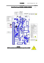
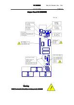
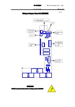
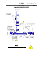
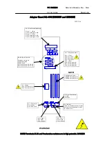
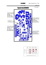
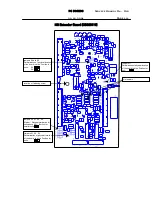
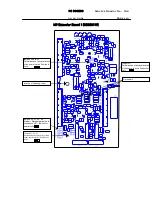
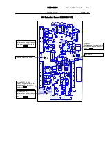
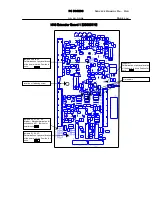
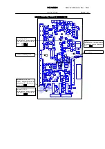
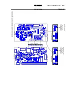
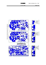
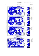
Signals and voltages are described on the layout drawings of the particular
boards. Instructions as introduced in procedure “Checking of current
measurement circuit” shall be used at trouble shooting of the Adapter boards.
9.4.6 Scaling resistors
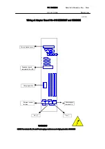
The scaling resistors R4, R5, R6, R7, and R8 are located on the Adapter
boards. Resistance values of the resistors are specified on chart
CX2ADAP.XLS, CX4ADAP.XLS and CX6ADAP.XLS in section 17. For location of
the resistors, look at layout drawings of the Adapter boards in section 9.4.3.
9.4.7 Settings on board
Any time, if the Adapter board has failed and will be replaced with a spare
board, type related settings of the current measuring circuit have to be done.
The spare board are not equipped with the scaling resistors by manufacturer.
For information of the settings to be done, look at the charts and the layout
drawings introduced in section 9.4.3. The resistors are through hole type
resistors for easy assembly by regular tools, such as soldering iron.
9.4.8 Spare parts
Adapter boards.
Detailed information for the spare parts is available from spare parts lists in
section “SPARE PART LIST”.
9.5 Branching board
9.5.1 Description
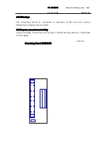
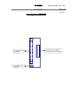
The branching board is used to connect signals from the Control board to the
Adapter boards in blocks B, C and D. The board is simple connector board
carrying all the signals for operation of inverter which generally are control
signals for the control of power stage and feedback signals to Control board.

