TROUBLESHOOTING
Service Manual M4 - M10
11.07.2002
Page
55
Frame size M8, M9 or M10, place jumper X12 on 1st Extender board (CB00119)
from left (not with expander board CB00019). Use X4 jumper from control
board.
Safe procedure to power up the drive is to use an external adjustable power
supply (see 5.4.2 Basic tool requirements).
To power up the drive under investigation, disconnect wire harness from
connector X8 on Power board(s). With power board CB00042 or CB00055
remove also SCR gate connector X19! With new power board (CB00055 M10
400/500V and CB00042 M8 to M10 690V) layout it is possible to disconnect DC+
from main circuit by pulling jumper X22 off and connect external power supply
to “AMP” connector X21. Remove always jumper from each power board. With
this power board it is not required to disconnect X8 or X19!
Connect lead from (+) terminal of the external power supply to connector X8-1
(or to connector X21) on the Power board and respectively (-) terminal of the
external power supply to negative bus of the drive.
NOTE! It is important to disconnect wire harness (or jumper X22) from each
Power board. Otherwise DC bus will charge up trough not disconnected power
board! When circuit boards are powered, measure DC bus voltage that it is
zero! The unpowered main circuit reduces risks for destructive damages
within inverter, if defections exist in control or main circuitry.
The gate signals will be measured by oscilloscope from output of each pulse
amplifier (from each phases, both upper-, and lower leg circuitry).
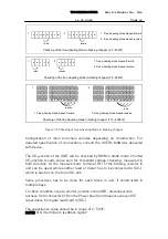
For the measurement, test adapter will be connected to connector on the
Power board once wire harness is disconnected from the connector. The gate
leads will be connected to the adapter as figure below shows
X9
1
2
4
5
Gate leads
Adapter
Points to connect probe
Connection Power board - Adapter - Gate leads
X9
1 - 2
U, lower leg
X9
4 - 5
U, upper leg
X11
1 - 2
V, lower leg
X11
4 - 5
V, upper leg
X13
1 - 2
W, lower leg
X13
4 - 5
W, upper leg
Figure 7.3 Connection Power board – Adapter – Gate leads


