TROUBLESHOOTING
Service Manual M4 - M10
11.07.2002
Page
59
L1
L2
L3
R-
R+
L1
L2
L3
R-
R+
1.
2.
~0,6V
Infinite
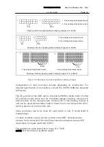
1. Free wheeling diode biased forward
2. Free wheeling diode biased reverse
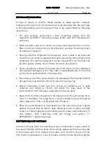
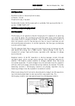
Checking of the free wheeling diode in braking chopper (2,2 - 45kW)
U
V
W
U
V
W
R-
R+
R-
R+
1.
2.
~0,6V
Infinite
U
V
W
U
V
W
L1 L2 L3
U
V
W
+
~0,6V
Infinite
1.
2.
1. Free wheeling diode biased forward
2. Free wheeling diode biased reverse
Checking of the free wheeling diode in braking chopper (55 - 90kW)
1. Free wheeling diode biased forward
2. Free wheeling diode biased rewerse
Checking of the free wheeling diode in braking chopper (110 - 400kW)
L1 L2 L3
U
V
W
+
R1
R2 R3 R4
R1
R2
R3 R4
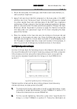
Figure 7.5 Checking of free wheeling diode in braking chopper
Configuration of main terminals variates depending on construction. For
detailed specification of connections, consult the USER’s MANUAL delivered
with device.
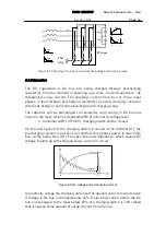
The CE-junction of the IGBT will be checked by DMM in diode mode. Shorted
CE-junction results value zero for threshold voltage checking, measured in
both direction. At the measurement, terminal (R-) of the braking resistor in
unit can be used, while another lead of meter has to be connected to (DC-),
which is bus bar on the top in DC-link.
Same procedure has to be done for each block in unit, if constructed in
multiple bays.
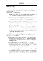
To check condition of gate-emitter junction of the IGBT, disconnect wire
harness from connector X18 on the Power board and measure value of CE
capacitance from gate lead (red) to (DC-).
The capacitance value should be in range of 2 - 50nF.
NOTE! X18-3 terminal is feedback signal!


