MAIN
CIRCUIT
Service Manual M4 - M10
29.12.1999
Page
62
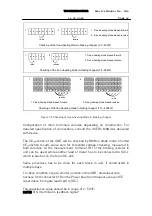
Six pulse rectifier rectifies three phase line power to DC power. The line
reactor provides good protection for the rectifier against voltage spikes and
transients entering from the line. Current through the diodes in the rectifier is
divided in order of instantaneous voltage on the line. In normal conditions, as
operation on line where impedances are equal in each phases, RMS values of
phase currents are equal.
8.2.3 Troubleshooting
Before any test measures, make sure that the DC bus is discharged and
remaining voltage does not exist. Clear all possible baths for entering
electricity, such as input line, possible bypass connections, etc. for safe
working environment.
Diode checking can be performed by digital multimeter (DMM) in resistance
mode, or more likely in diode checking mode, if available.
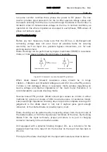
~0.6V
~10kohm...100kohm
Infinite
Forward biased PN-junction
Reverse biased PN-junction
Figure 8.1 Forward / reverse biased PN junctions
When diode biased forward, resistance value should be in range
10kohm....100kohm and threshold voltage around 0.5V cross the PN junction,
if diode is not damaged. Value in resistance mode variates depending on
source voltage and internal impedance of the multi meter therefore it is
recommended to use diode checking mode.
Reverse biased PN junction (diode) should give values as infinite in either
methods (or points out couple of Ohm resistance value in resistance mode).
Low power/high impedance checking does not provide complete coverage for
judgement is the diode intact or not, but it anyhow gives good enough
indication, of the shorted diode or possibly open circuit.
Diode checking can be performed by measuring values from the terminals of
the diode module, or from the input power terminals of the drive. By checking
diodes from the input terminals, proper procedure is to pull in charging
contactor manually in the units where exists.
Unit equipped with a dynamic braking chopper, DC- as a reference for the
measurement has to be taken from the bus bar on the top of two bus bars in
DC-link.
Principle of the diode checking from the input terminals described on below.


