MAIN
CIRCUIT
Service Manual M4 - M10
29.12.1999
Page
64
can assumed to be reason for the phenomena. Normally loose connection in
power terminals activates function of input line supervision and causes
tripping and fault indication F10 on display.
Open circuitry in the rectifier module cannot be picked up by the input line
supervision function. The open circuit causes increased voltage ripple in DC
bus and voltage RMS value to be dropped. Level of voltage in DC bus is
directly proportional to the voltage at mains. In three phase system
rectification factor is 1.35 which equals with formula:
(6*
√
2)/(2*
π
)=1.35 => Udc=Uin*(6*
√
2)/(2*
π
),
When rectifier is loaded and all three input phases supply energy evenly. If for
some reason one of the input phases is missing (assumption: failure cannot
be indicated by the function of the input phase supervision), voltage level in DC
bus is rectified from two phases to charge DC capacitors to level Udc=Uin*0.9,
when rectifier is loaded. The rectification factor 0.9 is result of two phase, four
pulse rectifier and matches with formula:
0.9 = (4*
√
2)/(2*
π
).
Design and rating of DC-link supports ripple in range of 270 - 396Hz with
hold-up capacity accordingly to ripple generated by 45...66Hz line frequency in
three phase system to provide smooth enough DC energy for proper operation
of motor control.
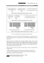
Next figure 8.5 is waveform of DC bus voltage, when rectifier is normally
loaded and the three phase supply supplies energy evenly from each phases.
Udc(max)
Udc(min)
Figure 8.5 Principle of voltage waveform on DC bus.
Proportional value of voltage ripple generated by line commutated, loaded
rectifier follows formula
Udcripple(%)=((Udc(max)-Udc(min))/(Uline*6*
√
2)/2*
π
))*100
In reality, level of the voltage ripple in the DC bus should not be higher, than
15% of the ideal DC voltage.


