MAIN
CIRCUIT
Service Manual M4 - M10
29.12.1999
Page
65
8.2.4 Assembly instructions
In case of failure in rectifier (diode module or diode thyristor module),
multiple parts’ electrical connections have to be disconnected, the part have
to be disassembled and the new part have to be reassembled by following
instructions:
1.
For safe working environment, check remaining energy from DC
capacitors by DMM, if remaining voltage exists, wait until discharged to
safe level.
2. Mark-up cables and wires which are being disconnected from circuitry.
After electrical connections are disconnected, unscrew mounting screws
of module to release it.
3.
Clean up thermal compound from heat sink, even it looks to be clean and
clear there can be dirt, especially hard particles among remaining thermal
compound. The thermal compound can be cleaned off from the heat sink
by some grease cutting, non corrosive chemical, like ethanol.
4.
Check installation surface of the heat sink, from dents, bursts, unflatness
and possible damages, which may affect unadvantageously for thermal
junction from semiconductor to the heat sink.
5.
Clean base plate of the semiconductor by sweeping it the first with ethanol
damped clean rag and after that with clean dirt free dry rag.
6.
Before installation, make sure that screws for fastening are in good
condition and length is correct and check the base plate of the
semiconductor from damages, especially on the base plate.
7.
Apply fresh thermal compound on the base plate of the semiconductor to
cover it completely. The applyment is recommended to be performed by
roller. Details for roller can be asked from Producer.
8.
Place the semiconductor in right position on the heat sink, press it lightly
against the heat sink by hands, align fastening holes on place, pretight
screws in. Follow tightening order and torque for power semiconductors in
next chapter “8.2.5 Tightening order and torque” and section “17.
APPENDIXES” / tightening torque.
8.2.5 Tightening order and torque
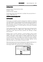
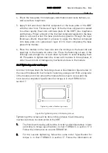
An order to torque down the fastening screws is illustrated on figure below. In
the case of module with four holes for fastening, always start from a long side
of the module and circle around the module from screw to screw until the
first round is completed. In case of module with two holes fastening tighten


