PC
BOARDS
Service Manual M4 - M10
22.10.2001
Page
78
9.
PC
BOARDS
9.1 General
Main goal in design process of the product was to achieve desired functions
with minimum quantity of different type of PC boards. This requirement was
leading to another approach, how to have enough flexibility into design to get
the PC boards to be used cross the product range in variously rated drives.
The challenge was solved with an idea to make part of the circuitry flexible to
be modified according to type of the unit it was designed to be fitted. In
following sections used PC Boards with required settings are described with
detailed information.
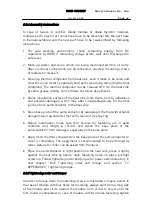
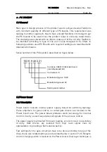
Serial number of the PC boards is described on figure below:
9.2 Power board
9.2.1 Description
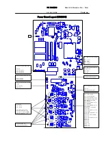
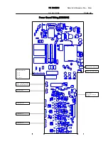
Power board consists internal power supply, based on switching topology.
Pulse amplifiers for gate control, so called gate drivers are located on the
Power board also. The power board produces electrical energy for internal
control circuitry, as well as purposes of signals of the process control.
The power supply is protected from over loading, or short circuit in secondary
circuitry. Gate drivers are isolated from logic level signal lines by
optoisolators to providing 2,5kV isolation barrier.
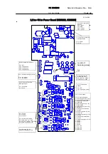
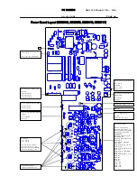
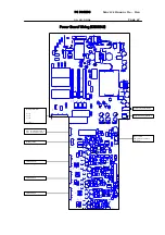
Few settings for the gate circuitries have to be done according to type of the
drive, these size related settings are described below in section 9.2.6. Relay to
control charging switch is located on the Power board. Dual layer technique is
103 K 9 48 021
Card type: CB00103 Extender board
(look at sparepart list)
Card version: K
Manufacturing year: 1999
Manufacturing week: 48
Running serial number


